Hello! Welcome back to our hands-on exploration of the CAN protocol.
In our last lesson, you successfully configured the low-level bit timing for our STM32's CAN peripheral, setting a bus speed of 500 kbit/s. This was a critical step; with the hardware connected and the timing synchronized, our node is now physically capable of participating in a CAN network.
Today, we will move from physical configuration to application-level logic. Our goal is to implement a function to transmit a standard CAN message. You will learn how to construct a CAN data frame in software by defining its identifier and payload, and then use the STM32 HAL library to queue this message for transmission onto the bus.
1. Anatomy of a Transmit Message
Before writing code, let's quickly review the structure of a standard CAN data frame. While the CAN protocol involves many fields (arbitration, control, CRC, ACK), the HAL library simplifies our task, allowing us to focus on the parts that carry our application's information.
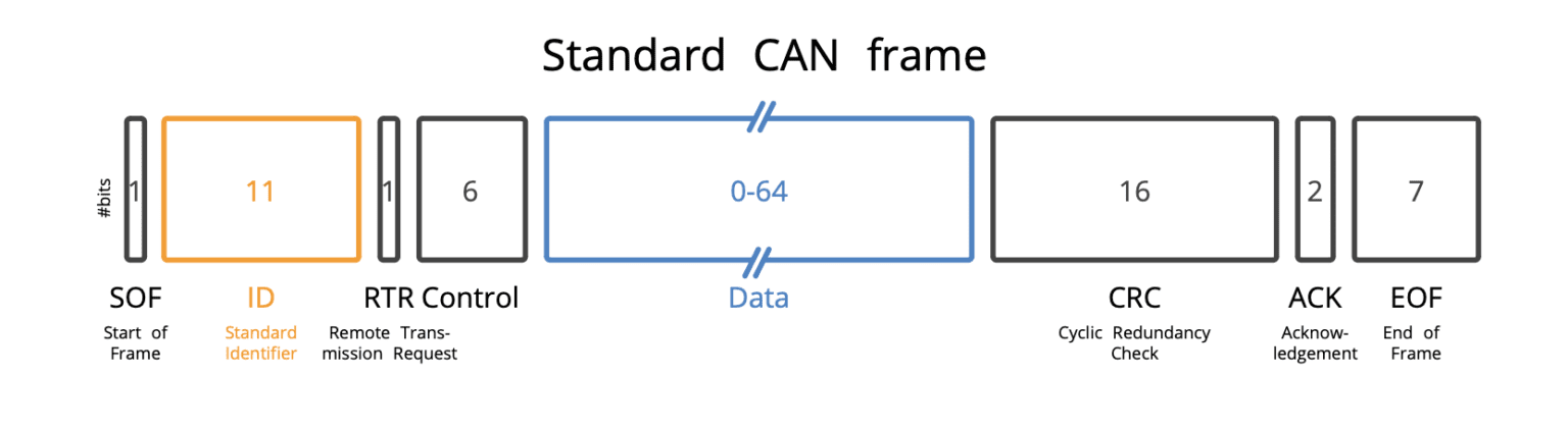
To send a message, we need to specify three key elements:
- The Header: This contains the metadata of the message.
- Identifier (ID): A unique 11-bit value (for standard frames) that dictates the message's priority. Lower IDs have higher priority. This is not a destination address; any node on the bus can choose to listen to this ID.
- Data Length Code (DLC): A number from 0 to 8 indicating how many bytes are in the data payload.
- Frame Type: We must specify if we are sending a Data Frame (to transmit information) or a Remote Frame (to request information). Today, we will send a Data Frame.
- The Payload: This is the actual data we want to send, consisting of 0 to 8 bytes.
The STM32 HAL provides convenient structures and functions to package and transmit this information.
2. Preparing the Message in Code
To send a CAN message using HAL, we need to declare three variables in our C code. These will typically be placed before the main function or within main before the while(1) loop.
/* Private user code ---------------------------------------------------------*/
/* USER CODE BEGIN 0 */
CAN_TxHeaderTypeDef   TxHeader;
uint8_t               TxData[8];
uint32_t              TxMailbox;
/* USER CODE END 0 */
Let's break these down:
CAN_TxHeaderTypeDef TxHeader;: This is astructdefined by the HAL library that holds all the header information (ID, DLC, etc.).uint8_t TxData[8];: This is a simple byte array that will serve as our data payload. We declare it with a size of 8, the maximum possible.uint32_t TxMailbox;: The STM32'sbxCANperipheral has three internal transmit buffers, called "mailboxes." When we ask HAL to send a message, it finds an empty mailbox, places our message in it, and flags it for transmission. This variable will be used by the HAL function to inform us which of the three mailboxes (0, 1, or 2) was used.
Now, let's see how to populate the header and data before sending. The following video provides a clear, step-by-step guide to this process.
STM32 CAN: Loopback Mode + Filter Setup Guide
This video from ControllersTech provides a detailed walk-through of setting up the transmit header and using the HAL function to send a message. It directly aligns with our goal for today.
Watch the segment from 09:15 to 11:41. Focus on how each field of the CAN_TxHeaderTypeDef struct (DLC, IDE, RTR, StdId) is configured. Pay close attention to the final call to HAL_CAN_AddTxMessage and its parameters.
As shown in the video, we configure the TxHeader struct and the TxData array with our desired message contents. Here is a typical example:
// In your main function, before the while(1) loop or inside it

// 1. Configure the header
TxHeader.StdId = 0x123;          // A standard 11-bit ID
TxHeader.IDE = CAN_ID_STD;       // Specify it's a standard ID
TxHeader.RTR = CAN_RTR_DATA;     // Specify it's a data frame
TxHeader.DLC = 2;                // Data Length Code: 2 bytes of data
TxHeader.TransmitGlobalTime = DISABLE;

// 2. Prepare the data payload
TxData[0] = 0xDE;
TxData[1] = 0xAD;
3. Transmitting the Message with HAL
With the header and data prepared, the final step is to call the HAL function that queues the message for transmission.
HAL_StatusTypeDef HAL_CAN_AddTxMessage(CAN_HandleTypeDef *hcan, CAN_TxHeaderTypeDef *pTxHeader, uint8_t aTxData[], uint32_t *pTxMailbox);
This function takes four arguments:
- A pointer to your CAN handle (
&hcan). - A pointer to your configured header (
&TxHeader). - The data payload array (
TxData). - A pointer to the mailbox variable (
&TxMailbox).
A successful call to this function returns HAL_OK. It's always good practice to check this return value to handle potential errors, such as if all three transmit mailboxes are already full.
For a textual reference with code snippets you can copy, this tutorial from ControllersTech is an excellent resource.
STM32 CAN Bus Communication Tutorial
This article provides the complete code structure for transmitting a CAN message, from variable declaration to the final function call. It serves as a great reference to follow along with.
Read the section titled "Transmitting the CAN Data Frame in STM32". This section covers preparing the TxHeader and TxData and using HAL_CAN_AddTxMessage. The code snippets are directly applicable to your project.
4. Hands-On Implementation
Now it's time to put this into practice.
-
Open your project in STM32CubeIDE.
-
Declare the variables: In
main.c, add theTxHeader,TxData, andTxMailboxvariable declarations in the/* USER CODE BEGIN 0 */section. -
Start the CAN peripheral: The CAN peripheral needs to be explicitly started. In your
main()function, after the call toMX_CAN_Init(), add the following line:/* USER CODE BEGIN 2 */ if (HAL_CAN_Start(&hcan) != HAL_OK) { /* Start Error */ Error_Handler(); } /* USER CODE END 2 */ -
Add the transmission code: Inside the
while(1)loop, add the code to configure the header, prepare the data, send the message, and add a delay./* Infinite loop */ /* USER CODE BEGIN WHILE */ while (1) { // Configure the header TxHeader.StdId = 0x123; TxHeader.IDE = CAN_ID_STD; TxHeader.RTR = CAN_RTR_DATA; TxHeader.DLC = 2; // Sending 2 bytes TxHeader.TransmitGlobalTime = DISABLE; // Prepare the data payload TxData[0] = 0xBE; // Some data TxData[1] = 0xEF; // Some more data // Add the message to the Tx mailboxes and send if (HAL_CAN_AddTxMessage(&hcan, &TxHeader, TxData, &TxMailbox) != HAL_OK) { /* Transmission request Error */ Error_Handler(); } // Wait 1 second before sending the next message HAL_Delay(1000); /* USER CODE END WHILE */ /* USER CODE BEGIN 3 */ } /* USER CODE END 3 */ -
Compile and Flash: Build your project and flash it to your STM32 board.
Your microcontroller is now transmitting a CAN message with ID 0x123 and a payload of [0xBE, 0xEF] every second! While you can't see the message without a second CAN node or an analyzer, you can verify success in software. By placing a breakpoint after the HAL_CAN_AddTxMessage call and running the debugger, you can inspect its return value. If it's HAL_OK, the request was successful and the hardware has taken over. You can also inspect the TxMailbox variable; it should contain a 0, 1, or 2, indicating which hardware buffer was used.
Conclusion
Congratulations! You have successfully implemented one of the most fundamental operations in automotive firmware: transmitting a CAN message. You learned how to abstract the complex CAN frame structure using the HAL library, configuring only the essential application-level details like the message ID and data payload.
Key Takeaways:
- Transmitting a CAN message with HAL involves three main components: a header struct (
CAN_TxHeaderTypeDef), a data array (uint8_t[]), and a mailbox variable (uint32_t). - The header defines the message's identity (
StdId), type (IDE,RTR), and payload size (DLC). - The
HAL_CAN_Start()function is required to enable the CAN peripheral after initialization. - The
HAL_CAN_AddTxMessage()function queues a message for transmission in one of the three hardware mailboxes. - Checking the return status of HAL functions is a crucial part of robust firmware development.
So far, we're transmitting messages into the ether. In our next lesson, we will complete the loop by learning how to receive messages. You will configure the CAN hardware filters to listen for specific IDs and write an interrupt service routine to process incoming data.