Hello! Welcome to your sixth lesson in the "State Estimation" module.
In our last lesson, we successfully constructed the full state-space model of a Luenberger observer. We found that the observer itself is a linear system whose state is the estimated state , and whose inputs are the plant's control input and measured output . The key equation we derived was:
Today, we'll bring this theory to life. Our goal is to simulate an observer in MATLAB to visually and numerically confirm that the estimated states, , converge to the true system states, . This is the crucial verification step that proves our design works as intended.
The Simulation Strategy
To verify our observer, we need to compare its estimates to the "ground truth." Since we don't have a physical system on hand, we will simulate one. Our strategy involves four main steps:
- Simulate the "True" System: We'll define a plant model in MATLAB and simulate its response to a given input and initial condition. This will generate the true state trajectory and the true measured output .
- Design the Observer: We'll choose desired pole locations for the observer (making them faster than the plant's dynamics) and calculate the observer gain matrix .
- Simulate the Observer: We'll build the observer's state-space model using the equation above. Then, we'll feed it the input and output from our "true" system simulation and run a second simulation to get the estimated state trajectory .
- Compare and Verify: We will plot both and on the same graph to visually inspect the convergence.
The following video provides a complete, practical walkthrough of this entire process in MATLAB. We will use it as our guide for this lesson.
State-Space Observer Design and Simulation in MATLAB - Control Engineering Tutorial
This tutorial by Dr. Aleksandar Haber is an excellent, step-by-step demonstration of how to design, implement, and simulate a state observer in MATLAB. It covers all the steps we just outlined.
We will be working through this video in sections. For now, you can get a quick overview of what it covers.
Step 1 & 2: Simulating the Plant and Designing the Observer
First, we need our "ground truth" data. The video uses a double mass-spring-damper system, which is a great general example. The process involves defining the system matrices , specifying an input signal and initial conditions, and using MATLAB's lsim command to generate the true state and output data.
Simultaneously, we'll design our observer by selecting desired pole locations and using the place command to find the gain . As we've learned, we need to use the duality principle here, applying place to the transposed system matrices (A' and C').
Let's watch how this is done.
State-Space Observer Design and Simulation in MATLAB - Control Engineering Tutorial
Watch this segment of the video to see how to set up the true system model, simulate it, choose observer poles, and compute the gain L in MATLAB.
Please watch from 10:04 to 21:09. Pay close attention to: How the system matrices (A, B, C) are defined. The use of lsim to generate x_true and y_true from a set of initial conditions x0_true. The selection of pole_location for the observer. The crucial use of place(A', C', pole_location) to calculate L_transpose.
After completing these steps, you have:
- The true state history,
x_true. - The true output history,
y_true. - A calculated observer gain matrix,
L.
Step 3: Building and Simulating the Observer
Now for the main event. We will construct the observer as a separate state-space system in MATLAB. Recall our observer state equation:
This equation tells us exactly how to build the observer's system matrices:
A_obs = A - L*CB_obs = [B, L]C_obs = eye(n)(wherenis the number of states, since we want the output to be the full state estimate)D_obs = zeros(n, m+p)(wheremis #inputs,pis #outputs)
The most important part is correctly defining the input for the observer simulation. The term shows that the observer is driven by both the control input and the measured output of the plant. In MATLAB, this means we need to create a matrix where the first row(s) are the control input u and the next row(s) are the measured output y_true.
We also need to give the observer its own initial condition, x0_observer. To see the convergence happen, it's essential to choose an initial condition that is different from the true system's initial condition. A common choice is to start the observer at zero, x0_observer = [0; 0; 0; 0].
Test your understanding!
Why is it crucial to simulate the observer with an initial state that is different from the true system's initial state ?
Show answer
The purpose of the simulation is to verify that the observer can correct its own errors and converge to the true state. If we start the observer with the exact same initial state as the plant (), the initial estimation error is zero. In an ideal simulation, the estimated state would perfectly track the true state from the beginning, and we would never see the error-correction mechanism in action. By starting them at different points, we create an initial estimation error, allowing us to see it decay to zero, which confirms the observer's stability and performance.
Now, let's see how to implement this final simulation step.
State-Space Observer Design and Simulation in MATLAB - Control Engineering Tutorial
This final segment of the video shows how to build the observer's state-space model, prepare its special input signal, and simulate it with lsim.
Please watch from 21:09 to 29:51. Focus on: How A_Observer and B_Observer are defined from A, B, L, and C. The creation of the combined input input_uy by stacking the system's input and its measured output y_true. The second call to lsim using the observer system, the combined input, and a zero initial condition for the observer. The final plots comparing the columns of x_true with the columns of x_observer.
Step 4: Visual Verification
The final step is to plot the results. By plotting the -th true state and the -th estimated state on the same axes for each state, we can visually confirm the performance of our observer.
You should see something like this:
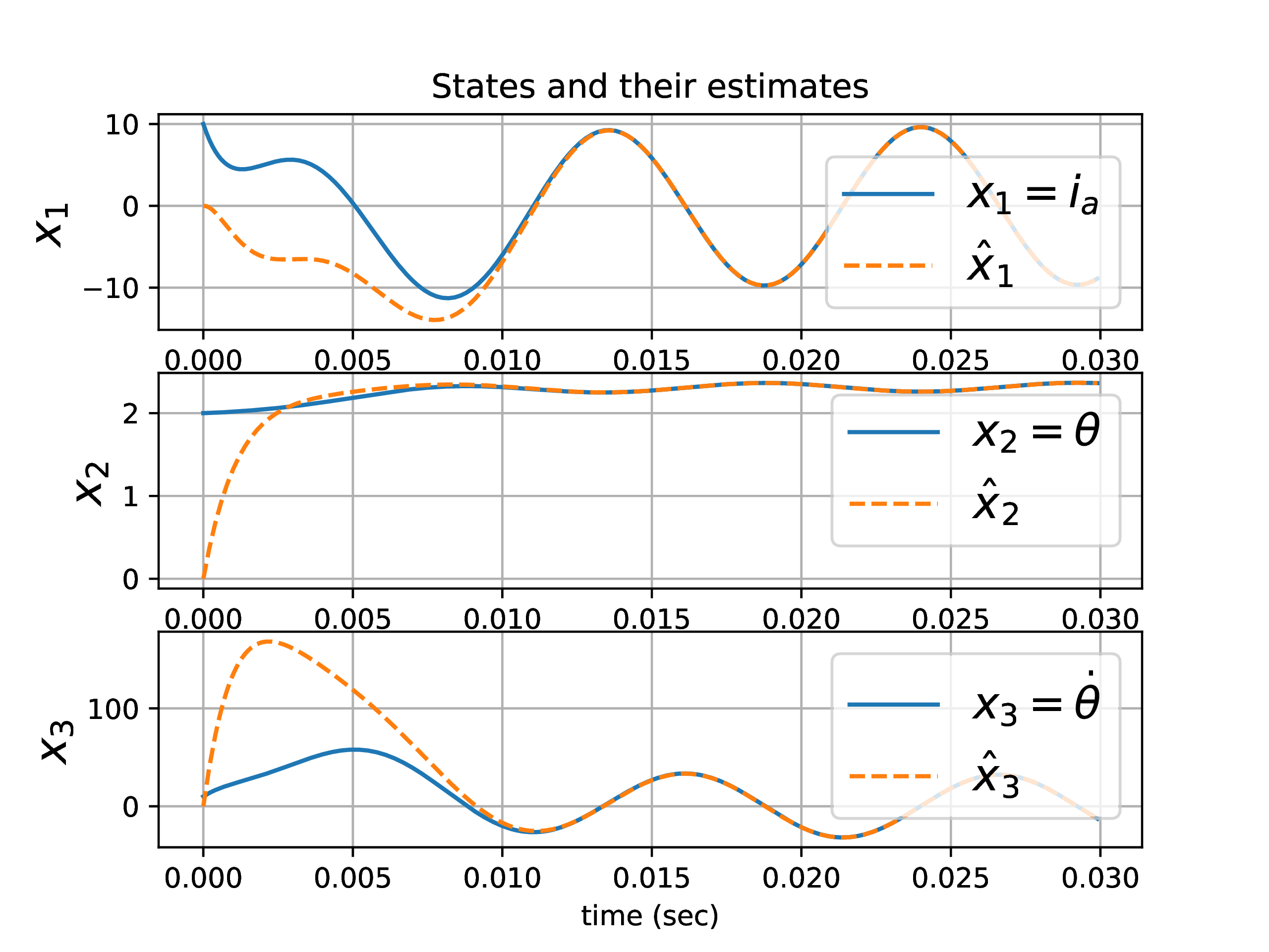
As seen in the video and the image above, the estimated states start from their own initial condition (zero in this case) and, after a brief transient period, converge to and track the true states. The speed of this convergence is dictated by the observer poles we chose in Step 2. If the estimates converge too slowly, you can move the observer poles further into the left-half plane.
The same procedure you've just learned for the mass-spring-damper system applies directly to any LTI system, including your rotary inverted pendulum project. The CTMS page on the inverted pendulum provides MATLAB code that follows a similar logic.
Inverted Pendulum: State-Space Methods for Controller ...
This resource from CTMS applies the same observer design and simulation principles to an inverted pendulum, which is directly relevant to your project.
Skim through the sections on observer-based control. You don't need to implement it now, but notice the key commands: poles = eig(Ac) to find controller poles, choosing P for observer poles to be faster, and using L = place(A',C',P)'. The final plot shows the system response, confirming the observer works well in the closed-loop context.
Conclusion
In this lesson, you learned the complete practical workflow for simulating a state observer to verify its performance. This process of simulating a "true" plant and a separate observer is fundamental to testing and validating your designs before deploying them on actual hardware.
Key Takeaways:
- To verify an observer, you simulate a "true" plant to generate and .
- The observer is constructed as its own state-space system with matrices and .
- The observer system is driven by a combined input signal composed of the plant's input and its output .
- By starting the observer from a different initial condition and plotting its states against the true states, you can visually confirm that the estimation error converges to zero at the rate determined by your chosen observer poles.
Preview of the Next Lesson:
We have successfully designed a controller (gain ) and an observer (gain ). Now it's time to put them together. The next lesson introduces the Separation Principle, a cornerstone of modern control theory. It states that we can design the state feedback controller and the state observer independently and then combine them, and the resulting closed-loop system will be stable. We will see how to implement the control law using our estimated states () and analyze the properties of the complete observer-based control system.