Hello! In the previous lesson, you translated between inverter and meter sign conventions while keeping measurement locations separate. That distinction now becomes a calculation: even after both readings use the same sign convention, aggregate PCS active power is not necessarily POI active power.
This lesson builds a power balance between the PCS AC terminals and the point of interconnection (POI). You will use specified transformer losses and auxiliary loads to calculate the difference in both discharge and charge operation—exactly the distinction a power plant controller (PPC) needs when interpreting a POI target.
Define the accounting boundary
The diagram below is a reminder that the batteries are only one part of a BESS. For this calculation, begin at the AC terminals of the power conversion systems (PCSs) and end at a specified POI meter. Transformers lie along the power path; auxiliary equipment such as cooling and controls consumes power, but its supply connection must be checked separately.
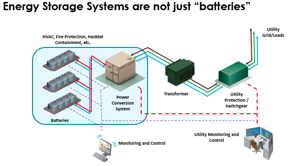
Define all active-power values here in a producer-positive convention: positive power means export toward the grid, and negative power means import for charging. Let
be the aggregate active power measured at the PCS AC terminals, and let be active power at the POI in the same convention. Specify transformer losses and relevant auxiliary consumption as nonnegative MW quantities.
If those losses and loads are inside the accounting boundary—between the PCS measurement and the POI measurement—the balance is
Equivalently, the signed difference is
The equation applies during charging as well as discharging. It says that transformer heat and auxiliary consumption reduce net export. During charging, “reduced net export” means more negative POI power, or greater grid import. It does not say that a charging PCS’s power magnitude becomes smaller at the POI.
A technical specification illustrates why the measurement boundary matters: it lists losses for equipment beyond the PCS AC terminals, as well as separate PCS efficiency. Read the loss list to see which quantities belong in a PCS-to-POI calculation.
A Scope of Works Sub Section – B Technical Specifications
Read the technical specification’s loss assumptions to distinguish losses downstream of the PCS AC terminals from PCS conversion losses, which are already reflected in a PCS AC measurement.
In “Losses Consideration,” start at the sentence beginning “The BESS Supplier shall take into consideration following loss parameters.” Read the loss list through the HT line entry. Note the stated boundaries for cable and transformer items; do not add every listed percentage to a calculation unless that equipment lies between the two measurement points you have defined.
Calculate the difference with specified MW losses
Suppose four PCSs are discharging at each, so aggregate PCS active power is . Over the same measurement interval, the specified transformer loss is , and auxiliaries supplied within the POI boundary consume . Assume these are the only intervening losses and loads.
The POI exports , not . The difference is , accounted for by the two specified terms.
Now use the same stipulated loss and load values at a charging operating point where aggregate PCS power is :
The PCSs absorb , while the POI imports . In a real plant, transformer loss can differ between the two operating points; the point here is how to use a loss when its value has been specified. Do not carry a measured discharge loss into a charge calculation without a reason to do so.
If the installed POI meter uses the import-positive convention from the previous lesson, convert only after completing the boundary calculation. It would report for the discharge example and for the charge example. A sign conversion alone would have produced in each case and missed the physical difference.
When a transformer loss is given as an efficiency
A specified loss in MW can be subtracted directly. A specified transformer efficiency needs more care because efficiency compares power entering and leaving the transformer in the direction of flow.
For a simplified transformer with efficiency , suppose auxiliaries are supplied elsewhere within the POI boundary, after the transformer in the discharge power path. On discharge at , the transformer delivers
With of those auxiliaries, POI export is . The transformer loss in this example is .
On charge, the direction through the transformer reverses. If the PCS terminals must receive , the grid side must supply more than to that transformer:
The transformer loss is therefore approximately . Adding the same auxiliary demand gives POI import of approximately , or in our producer-positive convention.
These numbers differ from the preceding examples because 98% efficiency produces different specified loss values; it was not a restatement of the earlier loss assumption. The useful rule is: if the required delivered power is known, divide by efficiency to find the power that must enter the transformer. Multiplying an charging demand by would incorrectly make grid import smaller than PCS demand.
Check whether auxiliaries belong in the POI balance
The subtraction of depends on where those loads are supplied and metered. If auxiliaries draw power on the plant side of the POI meter, their consumption affects that meter’s net reading. If they use a separately metered feeder outside the specified POI boundary, their consumption does not change the reading of that particular POI meter. You may need to report the separate auxiliary import for a broader site-wide balance, but you should not silently subtract it from a POI reading that excludes it.
The technical specification’s auxiliary-power test describes both a supply associated with the main point of connection and a separate auxiliary point of connection. Use that distinction to reinforce the boundary check, rather than assuming all auxiliary demand appears in one meter.
A Scope of Works Sub Section – B Technical Specifications
Return to the technical specification for its treatment of auxiliary power measurement. It shows why an auxiliary-load number needs a supply-point definition before it enters a PCS-to-POI balance.
In “3.7.4 Auxiliary Power Consumption Test,” begin with “Auxiliary Power Consumption shall be measured.” Read the measurement guidance through the sentence listing operating states. Focus on the two possible auxiliary supply points and on why consumption is recorded in different operating states.
There is one further boundary trap: do not subtract PCS conversion losses from a measurement already taken at the PCS AC terminals. Those losses concern the conversion between the battery/DC side and the PCS AC output. This lesson’s starting value is already on the AC side. Likewise, do not include a cable, transformer, or line loss that lies beyond the specified POI meter. Each term must sit between the two readings being compared.
For a PPC, this balance explains why commanding an aggregate PCS value equal to a desired POI value may leave a steady tracking difference. It does not, by itself, specify how to correct that difference: later lessons will address feedback control and operating limits. For now, the reliable calculation is to identify the boundaries, put readings in one sign convention, and include only the specified intervening losses and loads.
Key takeaways
With producer-positive readings at both locations, and with specified losses and auxiliary loads inside the POI boundary,
Thus PCS-to-POI differences reflect physical consumption, not merely opposite meter signs. On discharge, POI export is smaller than PCS output; on charge, POI import is larger than PCS absorption. When a transformer loss is supplied as an efficiency rather than MW, apply it in the actual direction of power flow.
The next lesson moves from accounting for a power difference to checking which active- and reactive-power operating points the PCS can actually provide.