Hello! Welcome back to our work on the capstone project.
In the last lesson, we focused on bringing realism and functionality to your desk design by integrating standard hardware from McMaster-Carr. You learned how to add screws and model features for heat-set inserts, creating a design that is not just a shape, but a buildable assembly.
Now that the desk's structure is well-defined, we can ask a critical engineering question: "Is it strong enough?" This lesson addresses exactly that. Our learning outcome is: Apply materials to components and perform a basic static stress analysis to identify weak points.
This is where your mechanical engineering background will be particularly useful. We'll be applying concepts of Finite Element Analysis (FEA) in a very practical way using Fusion 360's Simulation workspace. The goal isn't to get a perfectly precise numerical answer, but to gain valuable insights that allow us to compare design variations, identify potential problem areas, and build confidence in our design before we commit to manufacturing it.
1. Introduction to Static Stress Analysis
At its core, simulation allows us to apply virtual forces to our 3D models and see how they react. The most common and accessible type of simulation is Static Stress Analysis. It's "static" because it assumes the loads are applied slowly and steadily, without any sudden impacts or dynamic effects.
This analysis is perfect for answering questions like:
- Will this shelf bracket bend too much under the weight of my monitors?
- Where are the most likely failure points in my design?
- Is my part over-engineered? Could I save material and print time?
To get a solid overview of the simulation environment and the different types of studies available, let's start with a video from Lars Christensen, a well-known expert in the Fusion 360 community.
Simulation for Absolute Beginners — Fusion 360 — And Your Comments & Questions— #LarsLive 61
This video, "Simulation for Absolute Beginners," provides an excellent introduction to the Simulation workspace and the purpose of static stress analysis.
Please watch from 04:38 to 10:01. The first part introduces the static stress study, and the second part provides valuable context by briefly explaining the other simulation types available in Fusion 360.
2. The Simulation Workflow: A Step-by-Step Guide
The process of running a basic static stress analysis follows a clear, logical sequence in Fusion 360. We'll walk through these steps using a hypothetical shelf bracket for your desk as an example. Let's imagine this bracket needs to support a heavy monitor or a stack of books.
To begin, you would switch from the Design workspace to the Simulation workspace and select Static Stress as the study type. From there, the workflow generally moves from left to right across the toolbar.
Step 1: Apply Materials
A simulation is meaningless without knowing what the object is made of. The material's properties (like its stiffness, or Young's Modulus, and its yield strength) are fundamental to the calculation.
First, you assign a physical material to each component in your study. For your desk, this might be wood for the tabletop and a type of plastic like PETG or PLA for a 3D-printed bracket.
Simulation for Absolute Beginners — Fusion 360 — And Your Comments & Questions— #LarsLive 61
Let's return to Lars's video to see how to assign and verify materials for a study.
Watch the segment from 12:01 to 13:12. Notice that you can either use the material assigned in the Design workspace or override it specifically for the simulation study.
Step 2: Apply Constraints
Next, you must tell Fusion 360 how the part is held in place. These are the constraints. A part floating freely in space with a force applied to it would simply accelerate away. We need to "fix" it realistically. For a shelf bracket, this would typically involve fixing the surfaces where it will be screwed to the desk or wall.
Getting the constraints right is arguably the most critical part of setting up a simulation.
Simulation for Absolute Beginners — Fusion 360 — And Your Comments & Questions— #LarsLive 61
This part of the video explains how to apply fixed constraints to represent where the part is bolted down.
Watch from 18:11 to 20:26. Pay attention to how he selects the inside of the bolt holes to simulate the part being securely fastened.
Step 3: Apply Loads
With the part constrained, you can now apply the loads—the forces it needs to withstand. For our shelf bracket, this would be a downward force on the top surface, representing the weight of the monitor. You can specify the force's magnitude (e.g., 200 Newtons, which is roughly 20 kg or 45 lbs) and direction.
Simulation for Absolute Beginners — Fusion 360 — And Your Comments & Questions— #LarsLive 61
Here's how to apply a structural load to the model.
Watch from 20:15 to 21:47. Note how you can select a face and specify the force magnitude. Once the setup has a material, constraints, and loads, the study is ready to be solved.
Step 4: Generate a Mesh & Solve
Before solving, the software must perform a step called meshing. It breaks your continuous model down into a large number of small, simple elements (often tetrahedra), creating a "mesh." The calculations are then performed on this mesh.
The finer the mesh, the more accurate the result, but the longer the calculation will take. For our purposes, the default settings are usually a good starting point.
After meshing, you solve the study. Fusion 360 gives you the option to solve it on your local computer or in the cloud. For simple studies, local solving is fine. Cloud solving is useful for very complex analyses or if you want to continue working on your computer while the calculation runs.
3. Interpreting the Results to Find Weak Points
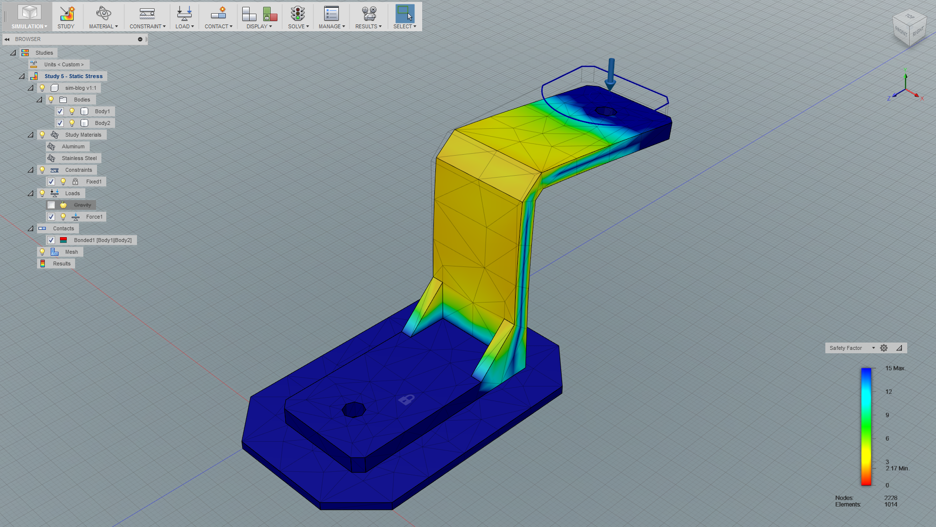
Once the simulation is solved, Fusion 360 presents the results as a color-coded plot overlaid on your model. Understanding what these colors mean is key to identifying weak points. There are three main results we are interested in.
Result 1: Safety Factor
This is often the first result you'll see. It's a simple ratio: Material Strength / Actual Stress.
- A safety factor less than 1 means the part is predicted to fail (permanently deform or break).
- A safety factor greater than 1 means the part should be strong enough.
- For DIY projects, a minimum safety factor of 2 or 3 is a good target to account for imperfections in material, manufacturing, and the simulation itself.
If your safety factor is very high (e.g., 15+), it may indicate that your part is over-engineered and you could potentially remove material to save cost and time.
Simulation for Absolute Beginners — Fusion 360 — And Your Comments & Questions— #LarsLive 61
Lars provides a clear explanation of the safety factor and what the typical design target is.
Watch from 23:41 to 26:01. The key takeaway is that a value below 3 warrants a closer look, and a value below 1 indicates likely failure.
Result 2: Stress (von Mises)
While safety factor tells you if the part is likely to fail, stress tells you where it's most likely to fail. The von Mises stress is a single value that represents the overall state of stress at a point in the material. The red areas on the stress plot highlight the "hotspots" or weak points where stress is concentrated. These are the areas you may need to reinforce, perhaps by adding a fillet or increasing thickness.
Simulation for Absolute Beginners — Fusion 360 — And Your Comments & Questions— #LarsLive 61
This segment shows how to switch to the stress plot and use the slider to identify the highest-stress regions.
Watch from 26:01 to 27:40. Using the stress plot is how you actively identify weak points for design iteration.
Result 3: Displacement
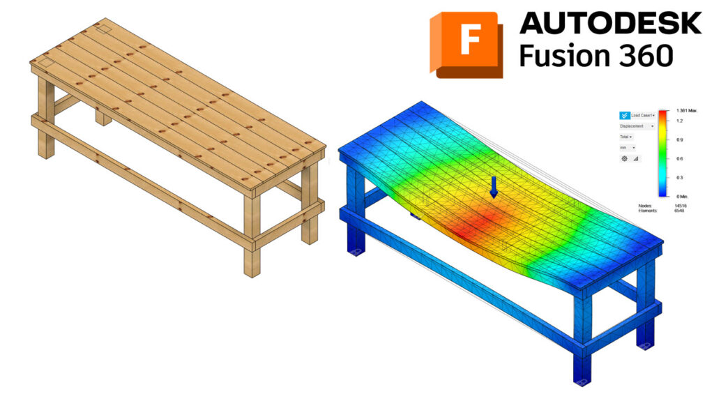
This plot shows how much your part physically moves or deforms under the load. While a part might not break (having an acceptable safety factor), excessive bending or sagging could still make it unusable. The displacement animation, though exaggerated, is excellent for visualizing the part's behavior under load.
Simulation for Absolute Beginners — Fusion 360 — And Your Comments & Questions— #LarsLive 61
Finally, let's look at displacement and the importance of the animation tool for understanding the results.
Watch from 27:24 to 32:45. This is a critical section. It not only explains displacement but also shows how an unrealistic animation revealed a flaw in the initial simulation setup (a missing wall constraint). This demonstrates the principle of 'garbage in, garbage out'—your results are only as good as your setup.
4. A Note on Simulating 3D Prints
The simulations we've discussed assume the material is isotropic—meaning it has the same strength in all directions. This is true for materials like steel but is not true for FDM 3D prints, which are anisotropic (stronger along the printed layers than between them).
Because of this, the Safety Factor result can be misleading for 3D prints. A more reliable approach is to look at the von Mises stress result and compare the maximum stress value to the known tensile strength of your filament.
SIMULATION in FUSION 360: IMPROVE the STRENGTH of your 3D prints!
Stefan from the CNC Kitchen channel provides an excellent insight into this specific challenge. His analysis is on a 3D printed bracket, which is very relevant to your goals.
Watch the segment from 08:00 to 08:50. He explains why, for anisotropic 3D prints, it's better to look at the von Mises stress value directly rather than relying on the calculated safety factor.
For example, if you find the maximum stress in your part is 30 MPa, and you know from testing that your PETG filament has a strength of around 45 MPa, you have a reasonable margin of safety.
Conclusion
You've now covered the fundamentals of performing a static stress analysis in Fusion 360. This is a powerful tool that allows you to test your ideas, identify weak spots, and optimize your designs before you even turn on the 3D printer or pick up a saw.
Key Takeaways:
- Static Stress Analysis helps predict how a part will react to steady loads.
- The core workflow is: Apply Materials, Apply Constraints (how it's held), and Apply Loads (the forces it must bear).
- The three key results are Safety Factor (is it strong enough?), Stress (where are the weak points?), and Displacement (does it bend too much?).
- Simulation setup is critical: your results depend entirely on how realistically you define the constraints and loads.
- For anisotropic materials like 3D prints, comparing the von Mises stress to the material's known strength is often more reliable than using the default safety factor.
Next Lesson Preview:
Now that you can model your desk and analyze its structural parts, the final step is to prepare the documentation needed to actually build it. In the next lesson, we will cover how to generate a Bill of Materials (BOM) to create your shopping list, and how to create a set of dimensioned drawings for fabricating the wooden components.