Hello! Welcome back to the final module of your capstone project design.
In our previous lesson, you learned how to set up and run a basic static stress analysis in Fusion 360. You saw how to apply materials, constraints, and loads to identify potential weak points using the Safety Factor, Stress, and Displacement plots. This is a huge step in moving from a simple 3D model to a validated engineering design.
But finding a problem is only half the battle. This lesson will focus on the other half: fixing it. Our learning outcome is to interpret stress analysis results and modify the design to improve structural integrity.
We will close the iterative design loop: Design -> Analyze -> Interpret & Modify. You'll learn how to read the simulation results not just as a pass/fail grade, but as a roadmap telling you exactly how to make your design better. We will explore common strategies for strengthening parts, from simple tweaks to adding new features, and how to verify that your changes have worked.
1. The Iterative Loop: From Analysis to Action
An engineer rarely gets a design right on the first try. The real power of simulation is its ability to facilitate a rapid, iterative improvement cycle. The results of one analysis provide the data needed to make an informed design change, which you can then re-analyze to check for improvement.
This cycle can be used to:
- Strengthen a weak design: Increase the safety factor from a failing value to an acceptable one.
- Optimize an over-engineered design: If a part is far stronger than it needs to be (e.g., a safety factor of 15), you can strategically remove material to save on print time and cost, then re-run the analysis to ensure it's still strong enough.
For a great example of this optimization process, take a look at the following blog post from Autodesk.
Introduction to Static Stress, and why every Designer should be using Simulation.
This article, "Introduction to Static Stress, and why every Designer should be using Simulation," demonstrates a complete iteration: analyzing a bracket, finding it's over-engineered, modifying it by reducing its thickness, and re-solving to confirm the new design is optimized.
Read the second half of the article, starting from the heading 'Next we will add a structural load...' to the end. Focus on the process: analyze (SF=15), modify (reduce thickness), and re-analyze (SF=4.5).
This loop is the core of what we'll be doing today. The key is making sure the "modify" step is guided by a proper interpretation of the results.
2. Reading the Results: What Are They Telling You?
When a simulation highlights a problem, your first step is to understand why it's happening. The colored plots for stress and displacement are your primary diagnostic tools.
Stress Concentrations
High-stress areas, often shown in red on the Stress plot, are frequently caused by stress concentrations. These occur where force is channeled through a small area, typically at sharp internal corners. From your mechanical engineering studies, you'll recall that stress is force divided by area ($\sigma = F/A$); by smoothing a sharp corner with a fillet, you increase the area over which the force is distributed, thereby reducing the peak stress.
Deformation Behavior
The Displacement plot is equally important. By animating the (exaggerated) deformation, you can see exactly how the part is bending, twisting, or sagging under load.
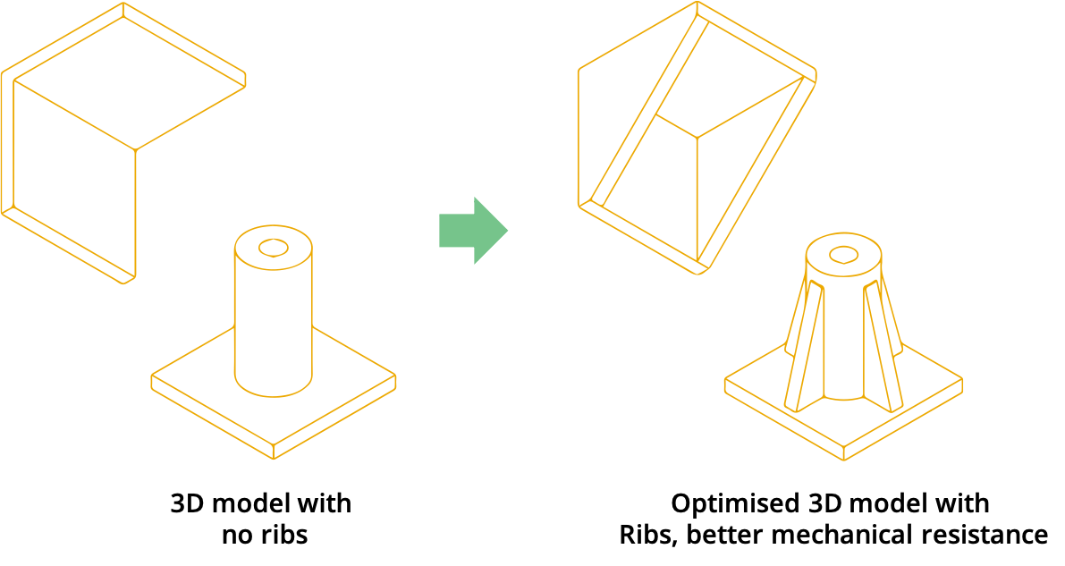
- Is a long, flat section bending? It might need a reinforcing rib.
- Is a corner flexing? It might need a triangular gusset.
- Is a slender leg collapsing? This could be buckling, a stability failure that can occur even at low stress levels. The fix is to make the part less slender by increasing its cross-sectional area.
3. Common Modification Strategies in Fusion 360
Once you've interpreted the results and have a hypothesis for how to fix the issue, you can return to the Design workspace to make changes. Let's look at a few common strategies.
Strategy 1: Changing Material
The simplest change, if your design allows it, is to switch to a stronger material. If your analysis shows a part made of ABS plastic fails, perhaps it needs to be made of aluminum or steel.
Fusion FEA for Beginners: Complete Stress Analysis Walkthrough
This video, "Fusion FEA for Beginners," starts with a perfect example of this. The initial analysis on a part made of ABS plastic shows a critical failure.
Watch from 15:02 to 16:13. Notice that the safety factor is far too low, making the presenter conclude that ABS is not a suitable material for the load, prompting an immediate switch to aluminum for the next iteration.
Strategy 2: Refining Geometry with Fillets
As discussed, fillets are the primary tool for combating stress concentrations at sharp internal corners.
Fusion FEA for Beginners: Complete Stress Analysis Walkthrough
Let's see this in action. The same video, after switching to aluminum, still shows a weak point. The presenter identifies it and makes a simple geometric change.
Watch from 16:13 to 18:39. He uses the 'Show weakest areas of design' feature to pinpoint a small fillet as the problem. He then switches to the Design workspace, increases the fillet radius using the Press Pull tool, and prepares to re-run the simulation.
Strategy 3: Adding Reinforcing Geometry
For issues related to bending or stability, you often need to add new geometry like ribs or supports. The displacement plot is your best guide for this.
Fusion FEA for Beginners: Complete Stress Analysis Walkthrough
In another example from the same video, the presenter analyzes an impact on a drone frame. The displacement plot clearly suggests a major design modification.
Watch from 34:35 to 36:50. He switches the view to Displacement and sees how the entire frame deforms. This leads him to conclude that adding support posts at the back would significantly improve the structure's integrity.
4. Verifying Your Fix and Validating the Simulation
After modifying your design, you need to verify that the change had the desired effect. The most effective way to do this is to re-run the simulation and compare the results.
Using the Compare Tool
Fusion 360 includes a powerful Compare feature that lets you view results from different studies side-by-side. This is ideal for A/B testing your design changes.
Fusion FEA for Beginners: Complete Stress Analysis Walkthrough
The Compare tool provides clear, visual confirmation of your design improvements. Let's see how it's used to compare the bracket design before and after increasing the fillet size.
Watch from 22:44 to 25:47. The presenter puts the original and modified results next to each other, allowing for a direct comparison of the safety factor, stress, and displacement, which quantifies the improvement.
A Crucial Note: Simulation vs. Reality
Finally, it is essential to remember that simulation is a guide, not a gospel. Its accuracy depends entirely on the assumptions you make during setup—especially your constraints. This is the classic "garbage in, garbage out" principle.
For your projects, especially with anisotropic 3D prints, the ultimate validation is a physical test. Simulation gets you 80-90% of the way there, but reality always has the final say.
SIMULATION in FUSION 360: IMPROVE the STRENGTH of your 3D prints!
Stefan from the CNC Kitchen channel provides a masterclass on this topic. He compares his simulation of a 3D printed bracket to a real-world destructive test and uncovers a flaw in his simulation setup.
Watch from 18:26 to 20:59. His optimized bracket fails in a way the simulation didn't predict. He realizes his boundary conditions were too simplistic and that a real-world screw connection doesn't behave like a perfectly frictionless support. This is a vital lesson in engineering: use real-world tests to validate and refine your simulation model.
Conclusion
You have now completed the entire iterative design and analysis loop. By interpreting the results of a simulation, you can make targeted, effective changes to your model and verify their impact, leading to stronger, more efficient designs.
Key Takeaways:
- Analysis drives modification: Use the Stress and Displacement plots to understand why and how a part is failing.
- Match the fix to the problem: Use fillets for stress concentrations, and ribs or gussets to counter bending and buckling. Changing materials is also a powerful option.
- The iterative loop is key: Modify, re-solve, and use the
Comparetool to confirm that your changes have improved the design's structural integrity. - Simulation is a guide, not a guarantee: Your assumptions (especially constraints) are critical, and for important parts, physical testing is the ultimate proof.
Next Lesson Preview:
Now that you have designed, assembled, and analyzed your capstone desk project, the final step is to prepare the documentation needed for manufacturing. In the next lesson, you will learn how to generate a Bill of Materials (BOM) to create a comprehensive list of all parts and hardware. This will be the first step in creating a full technical data package for your project.