Hello! Welcome to the next lesson in your capstone project documentation.
In the previous lesson, we closed the design-and-analysis loop. You learned how to interpret stress analysis results to identify weak points in your desk design and, more importantly, how to make targeted modifications—like adding fillets or reinforcing geometry—to improve its structural integrity. You now have a robust and validated digital model.
This lesson shifts our focus from design to manufacturing. A great design is only useful if you can actually build it. To do that, you need a precise inventory of every single piece required. Our learning outcome today is to generate a Bill of Materials (BOM) including a hardware list, wood cut list, and 3D printed parts list.
We'll transform your complex 3D assembly into a clear, actionable set of lists that will guide you through purchasing materials and fabricating your custom desk. Given your background in finance and engineering, you'll likely appreciate how a well-structured BOM serves as the "single source of truth" for a project's physical assets.
1. What is a Bill of Materials (BOM)?
A Bill of Materials (BOM) is a comprehensive list of all the raw materials, sub-assemblies, intermediate assemblies, sub-components, parts, and the quantities of each needed to manufacture a product. In the context of your desk project, it will break down into three key documents:
- A 3D Printed Parts List: A list of all the custom components you will print (e.g., cable clips, headset mount).
- A Wood Cut List: A detailed list of all wooden parts, including their final dimensions, for you to purchase and cut.
- A Hardware List: A list of all standard off-the-shelf parts like screws, bolts, and threaded inserts.
A complete and accurate BOM is essential for planning, cost estimation, purchasing, and assembly.
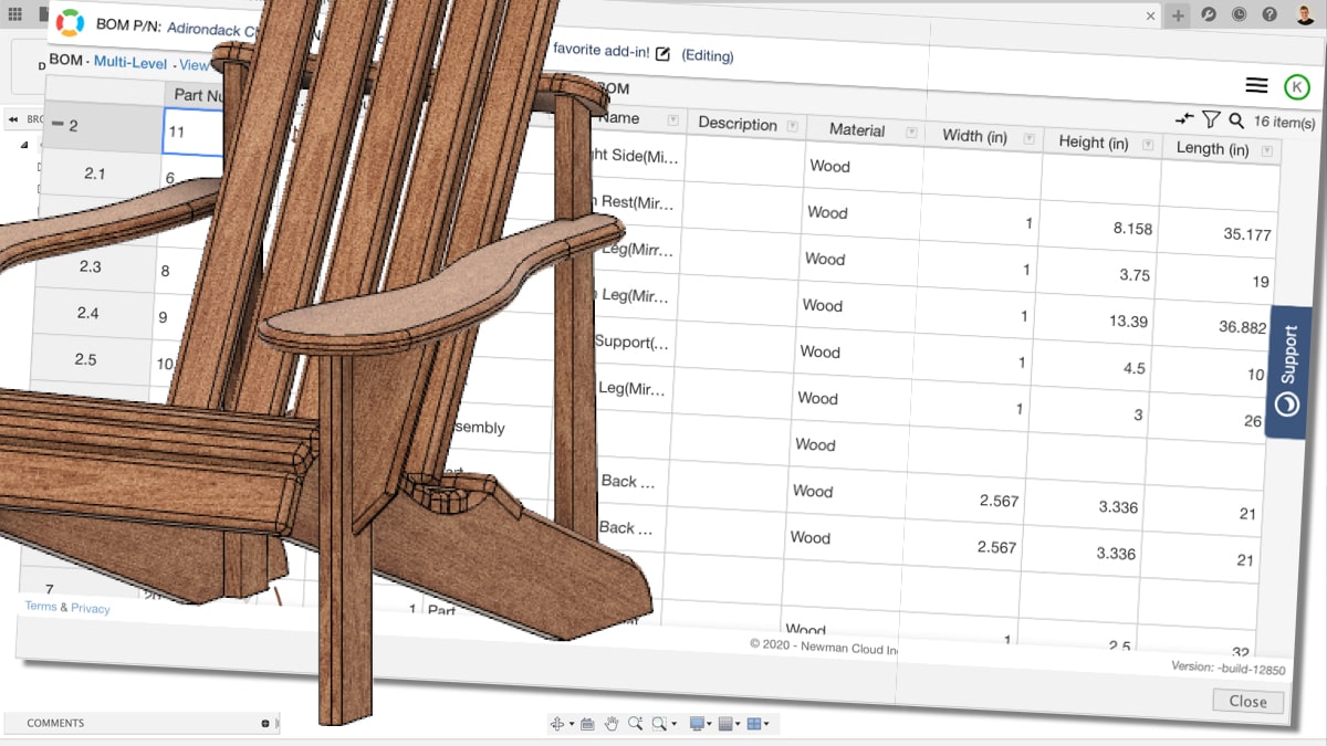

Fusion 360 offers a few ways to generate these lists, and we'll cover the most effective methods for your specific needs.
2. The Foundation: A Well-Structured Model
Before any list can be generated, your Fusion 360 model must be structured correctly. The software can't count what isn't properly defined.
To learn the two most critical rules for preparing your model, please watch the first part of the following video.
Parts List Fusion 360 - Fusion 360 for Woodworkers
This video, "Parts List Fusion 360 - Fusion 360 for Woodworkers" by Product Design Online, clearly explains the two essential prerequisites for creating an accurate parts list.
Watch from 00:43 to 02:59. Pay close attention to these two points: Every unique part must be a Component, not just a Body. To count identical parts correctly, you must use Copy or Pattern. Avoid using the Mirror command unless you are creating a distinct, non-interchangeable mirrored version (like a left-hand vs. a right-hand part).
Ensuring your model adheres to these rules is the most important step. If done correctly, generating the BOM becomes a much simpler task.
3. Generating a Hardware and 3D Print List
Your desk will use standard hardware (screws, nuts, etc.) and custom 3D printed parts. Both of these can be managed effectively using a standard Parts List in Fusion 360's Drawing workspace.
Step 1: Incorporating Standard Hardware
Manually modeling screws is time-consuming and unnecessary. Fusion 360's integration with the McMaster-Carr catalog allows you to insert pre-built, dimensionally accurate models of virtually any standard hardware.
Fusion 360: How to Insert PREBUILT McMaster-Carr Components in Autodesk Fusion 360 | #fusionFridays
This video from Product Design Online demonstrates how to insert McMaster-Carr components directly into your design.
Watch from 01:24 to 03:58. The key takeaway is how to find a part (like a screw or knob) and insert it. Notice that when the part is inserted, it's automatically created as a new component, and its name is set to the official McMaster-Carr part number. This is perfect for your hardware list.
By inserting hardware this way, you ensure that the correct part numbers will automatically populate your BOM, making purchasing much easier.
Step 2: Generating the Parts List
Once your model is organized into components and you've added your hardware, you can generate a master list. This is done in the Drawing workspace.
Parts List Fusion 360 - Fusion 360 for Woodworkers
Let's return to the "Parts List Fusion 360" video to see how this list is created and customized.
Watch from 02:59 to 10:31. This section covers the entire process: Creating a new drawing from your design. Placing a base view of your assembly. Inserting the Table (Parts List). Customizing the columns (e.g., Qty, Part Name, Description, Material). Editing component properties back in the Design workspace to populate the description and material fields, then updating the drawing to see the changes. This process will generate a list that includes your 3D printed parts and your hardware, with correct quantities and part numbers.
4. Creating a Dynamic Wood Cut List
The standard parts list is great, but for woodworking, you need a cut list with specific columns for Length, Width, and Thickness. The standard list doesn't easily pull these dimensions. For this, we'll use a more powerful tool: a Custom Table linked to your model's parameters.
Since your desk model is parametric, a custom table will automatically update if you change the desk's height, width, or any other driving dimension.
How to Use Custom Tables in Fusion Drawings
This video on a LinkedIn post by Fusion 360 expert Brad Tallis provides an excellent tutorial on creating a dynamic cut list using Custom Tables.
This video is embedded in a LinkedIn post; you can watch it directly there. Focus on these key concepts: Demonstration (00:00 - 02:05): See how changing model parameters automatically updates the cut list in the drawing. Creating the Table (02:05 - 03:30): Learn how to create a blank custom table and add static text for headers. Linking to Parameters (03:30 - 06:10): This is the most critical part. Understand how to double-click a cell and use the 'Properties' panel to link it to a specific component and one of its model parameters (e.g., 'door_width'). Driven Dimensions (06:10 - 08:35): Learn the solution for when a dimension you need for your cut list isn't an explicit parameter in your sketch (by creating a 'driven dimension').
Using a custom table gives you full control to create a professional cut list that is perfectly tailored for the woodworking portion of your project.
5. An Alternative: The Integrated BOM Tool
Recently, Autodesk introduced a new Bill of Materials feature directly within the Design workspace. This tool is excellent for quick data validation, collaboration, and exporting to spreadsheets without needing to create a formal drawing.
Introducing Bill of Materials (BOM) for Autodesk Fusion
This article from the official Autodesk Fusion Blog, "Introducing Bill of Materials (BOM) for Autodesk Fusion," explains the new feature.
Read the sections 'Working with the Fusion BOM' and 'Exporting Fusion BOM Content'. Key features to note are: Cross-highlighting: Selecting a part in the BOM list highlights it in the 3D model, and vice-versa. Live Data: The table is a live representation of your design's components. Exporting: You can easily export the BOM to a .CSV or .XLS file. This is particularly powerful for cost analysis or project management in Excel, which should be familiar from your finance work.
This integrated tool is a fantastic complement to the formal drawing-based parts lists. It's ideal for a quick export to a spreadsheet to plan your purchases.
Conclusion
You now have a complete toolkit for documenting every part of your capstone project. By turning your 3D model into concrete manufacturing lists, you've taken a major step toward making your design a reality.
Key Takeaways:
- A well-structured model (using components and correct copy methods) is the prerequisite for any accurate BOM.
- Use the McMaster-Carr integration to add standard hardware with correct part numbers.
- Generate a Parts List in the Drawing workspace for your master list, including 3D prints and hardware.
- Create a Custom Table linked to model parameters to build a dynamic and detailed wood cut list.
- Use the integrated BOM tool in the Design workspace for quick data validation and exporting to Excel for planning and costing.
Next Lesson Preview:
You have the "what" (BOM) and are ready for the "how" (fabrication instructions). In our next lesson, we will create dimensioned drawings. These orthographic views provide the detailed measurements needed to manually fabricate your wooden components and serve as a final piece of your project's technical documentation package.