Hello! Welcome back to the capstone project.
In our last session, you designed some excellent custom accessories for your desk—a parametric cable clip and a headphone holder. The cable clip, in particular, was designed to be fastened with a screw, which raises an important question: how do we account for standard hardware like screws, bolts, and nuts in our 3D models?
This lesson will answer that. Our learning outcome is to model and integrate standard hardware (screws, inserts) from a vendor library like McMaster-Carr.
Adding hardware to your designs is a crucial step for several reasons:
- Verification: It allows you to check for proper fit, clearance, and interference before you build or print anything.
- Realism: It makes your digital model a true "digital twin" of the final physical object.
- Documentation: It enables you to automatically generate a Bill of Materials (BOM), which is an essential part of any manufacturing plan.
We will start by adding a screw to the cable clip you designed, and then we will explore the best way to create strong, durable threaded connections in your 3D printed parts.
1. Integrating Hardware from Vendor Libraries
Instead of modeling common parts like screws from scratch, which is incredibly time-consuming, designers almost always import them from supplier catalogs. Fusion 360 has a fantastic built-in integration with McMaster-Carr, a massive distributor of mechanical and industrial parts.
Let's see what this is all about.
Fusion 360: How to Insert PREBUILT McMaster-Carr Components in Autodesk Fusion 360 | #fusionFridays
First, let's get a brief overview of what McMaster-Carr is and why its integration into Fusion 360 is so powerful. This short introduction from Product Design Online explains it well.
Watch the first two minutes of the video (00:00:00 - 02:04). The key takeaways are the time-saving benefits and how to access the catalog directly from the 'Insert' menu in Fusion 360.
Now that you know what's possible, let's walk through the actual process of adding a screw to the cable clip you designed in the previous lesson.
The Workflow: From Measurement to Assembly
The general process for inserting and positioning a standard part is as follows:
- Measure: Use the
Inspecttool to determine the exact size of the hardware you need. - Insert: Open the McMaster-Carr catalog and search for the part.
- Download: Select the part and download its 3D STEP file directly into your design.
- Position: Use the
Jointcommand to accurately position and constrain the hardware in your assembly.
Let's apply this to your cable clip. Please open the desk design containing the clip you modeled.
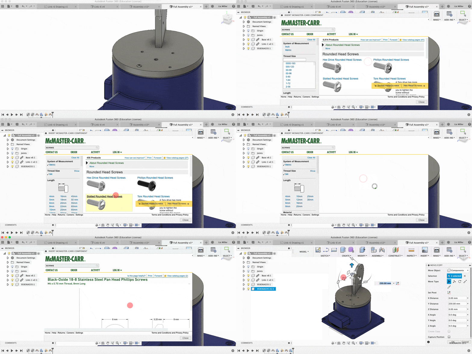
The following video provides a detailed, practical demonstration of this entire process. While the part shown is different, the steps are identical.
How to Insert Hardware in you Fusion360 Design
This video by MirageC provides an excellent, step-by-step guide to inserting and positioning hardware. We'll break it down into the key stages.
Follow these steps, using your cable clip design as the workpiece: Measure your part (00:57 - 01:39): First, use the Inspect tool (shortcut 'I') to measure the diameter of the screw hole in your cable clip. The clip was designed for an M3 screw, so you should find the diameter is 3mm. Find and Insert the Screw (01:39 - 02:58): Now, go to Insert > Insert McMaster-Carr Component. In the catalog, navigate to Screws & Bolts > Metric > Socket Head Cap Screws. Use the filters on the left to select M3 thread size and an appropriate length (e.g., 10mm). Click a part number, select 'Product Detail', choose 3D STEP as the format, and click 'Save'. Position with a Joint (02:58 - 06:17): This is the most important step. The screw will appear at the origin, unattached. The correct way to position it is with a Joint (shortcut 'J'). Pay very close attention to the technique shown at 03:45: Hold the Ctrl (or Cmd on Mac) key to lock the joint origin selection to a specific face. This is a critical skill. For the first joint origin, hover over the flat underside of the screw head, hold Ctrl, and select the center point. For the second joint origin, hover over the top surface of your cable clip's mounting tab, hold Ctrl, and select the center of the screw hole. Ensure the joint type is set to Rigid. The screw will snap perfectly into place.
By using a Joint instead of the Move command, you create a permanent relationship. If you move the desk or the clip, the screw will move with them.
2. Creating Threads in 3D Printed Parts
You've successfully added a screw to your model, but this brings up a physical consideration. If you screw a machine screw directly into a hole in a 3D print, the connection will be weak and will wear out quickly. For robust, reusable threads in plastic, the preferred method is to use heat-set threaded inserts.
These are small brass inserts with knurled outer walls. You press them into a slightly undersized hole in your print with a hot soldering iron. The plastic melts around the knurls and re-solidifies, locking the insert permanently in place.
A picture showing several threaded heat-set inserts installed flush into a blue 3D printed part.
Heat-set inserts provide strong, durable machine threads in 3D printed components.
Designing for Heat-Set Inserts
To use these inserts, you must design your parts with correctly sized holes.
Threading 3D Printed Parts: How To Use Heat-Set Inserts
This article from Hackaday is a comprehensive guide to using heat-set inserts. It covers the theory, design rules, and installation process. We will focus on the design aspects.
Please read the following three sections of the article. This will give you the necessary knowledge to correctly model features for these inserts. "Heat-Set Insert 'Theory'": This explains the basic principle of how they work. "Designing for Inserts": This is the most critical section for your CAD work. It discusses hole sizing (referencing datasheets) and the need to make the hole deeper than the insert to accommodate displaced plastic. "Slicer Settings": This provides a crucial link between your design and the physical printing process. The advice to increase the number of perimeters (walls) around the hole is essential for strength.
Modeling and Integrating an Insert
Now, let's apply this knowledge. We will model a hole for an M3 insert in the desk surface where the cable clip will be attached, and then we will insert a 3D model of the insert itself.
-
Find an M3 Insert: Go to McMaster-Carr again. Search for "heat-set inserts for plastics" and filter for M3 internal threads. A common choice is part number
94459A180. Look at its product detail page; it specifies a recommended hole diameter (e.g., 4.2mm) and has a CAD file you can download. -
Model the Hole: In your desk design, create a hole on the underside of the desk where you want to mount the cable clip.
- Use the dimensions from the McMaster-Carr datasheet. For part
94459A180, the insert is 4mm long. - Based on the Hackaday article's advice, make the hole deeper than the insert. A depth of 6mm would be appropriate (4mm for the insert + 2mm for displaced plastic).
- The recommended hole diameter is 4.2mm.
- Use the dimensions from the McMaster-Carr datasheet. For part
-
Insert the Component: Download the 3D STEP model for the M3 insert from McMaster-Carr.
-
Position with a Joint: Use a Rigid Joint to place the insert inside the hole you just created.
- Select the top edge of the insert as your first joint origin.
- Select the top edge of the hole in your desk as the second joint origin.
- The insert should now be perfectly seated in your model.
You now have a complete, realistic model of the assembly: the desk surface, the heat-set insert, the cable clip, and the screw holding it all together.
Conclusion
Great job! You have learned a critical skill for any designer creating functional assemblies. By integrating standard hardware, you bridge the gap between the digital model and the physical product.
Key Takeaways:
- Fusion 360's McMaster-Carr integration is a powerful tool for quickly adding standard hardware to your designs.
- The
Jointcommand is the correct method for positioning and constraining components in an assembly, creating robust relationships between parts. - For creating durable, machine-threaded connections in 3D prints, heat-set threaded inserts are the industry best practice.
- Successfully using inserts requires designing for them, which means modeling specifically sized holes and ensuring sufficient wall thickness in your part.
Next Lesson Preview:
Your desk model is now structurally complete and detailed with accessories and hardware. The next logical step is to analyze its strength. In the next lesson, which begins our final module on analysis and documentation, we will apply materials to components and perform a basic static stress analysis to identify potential weak points. Given your mechanical engineering background, this should be a very interesting application of your skills in a modern CAD environment.