Hello! Welcome back to your capstone project.
In the last lesson, you did some excellent work transforming the desk from a simple frame into a functional PC enclosure. You thoughtfully laid out component placeholders and designed crucial features for mounting, ventilation, and cable routing.
Today, we'll build on that by designing the custom accessories that bring convenience and organization to your setup. The learning outcome for this lesson is to design custom 3D printed accessories for the desk (e.g., cable clips, headset mount). This is a fantastic opportunity to apply your modeling skills to create small, practical parts that you can print and use. We will model two common accessories, each teaching a slightly different design approach.
1. The Parametric Cable Clip
First, let's tackle a fundamental desk accessory: a cable clip. You've already created passthrough holes for cables; now we'll design the clips to secure them. We will build a "P-clip" style that can be screwed into the underside of your desk. The key here will be using parameters to make the design adaptable for any cable size you might need in the future.
Step 1: Setting Up Parameters
A well-planned parametric model starts with defining the key dimensions. For our cable clip, these will be things like the wire diameter, the thickness of the clip, and the screw hole size.
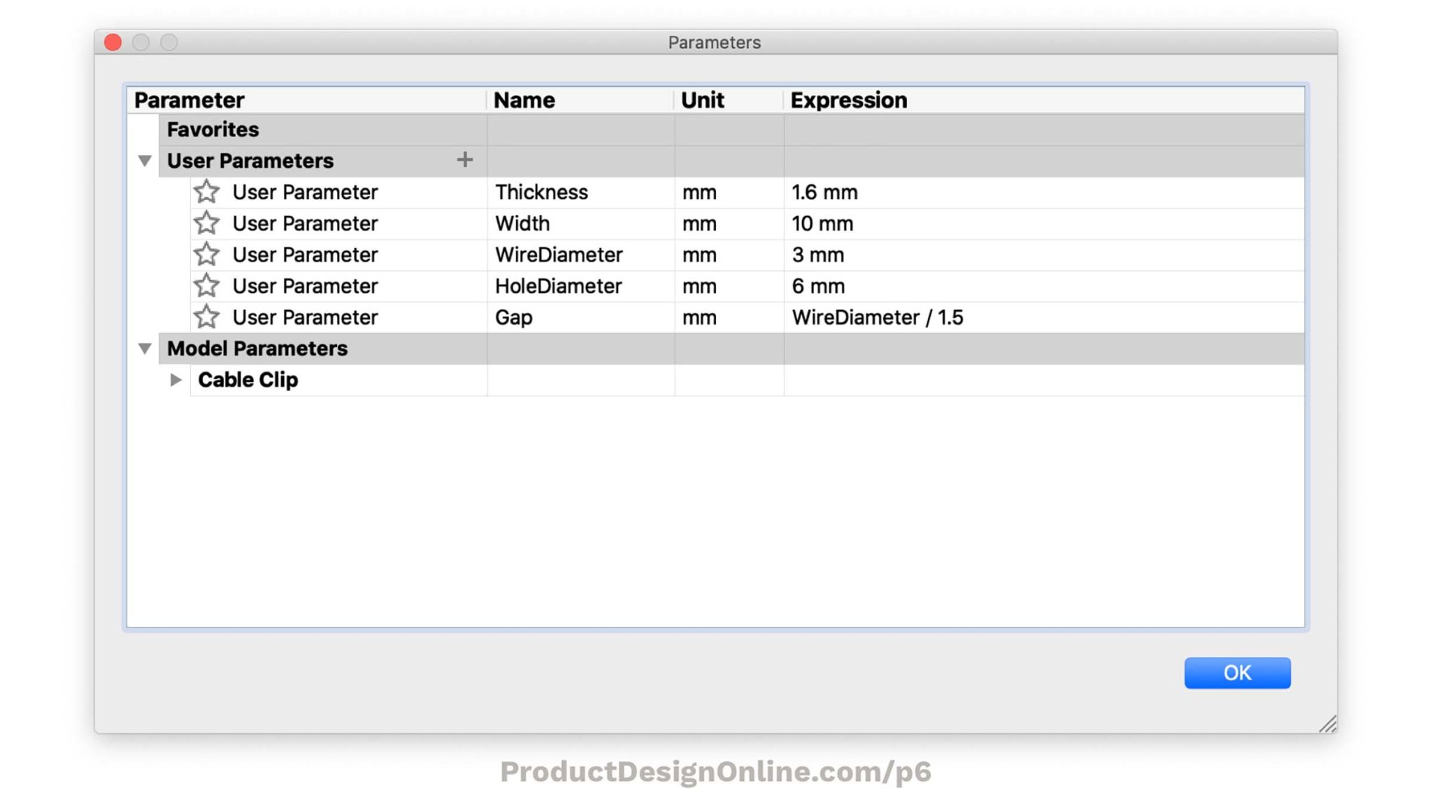
User Parameters for Cable Clip
Before we start sketching, let's set up the User Parameters that will drive our design. This article from Product Design Online provides the values we'll use.
Open the 'Change Parameters' dialog in Fusion 360 (Modify > Change Parameters). Under 'User Parameters', click the '+' icon and add the five parameters listed in the 'User Parameters' section of the article. You can use the image in the article as a reference. Notice how the 'Gap' parameter is defined by an equation using the 'WireDiameter' parameter.
Step 2: Modeling the Clip
Now that our parameters are defined, let's model the clip. We will follow a video tutorial that not only guides us through the sketch but also introduces a powerful alternative to the standard Extrude tool.
3D Printed Cable Clips with Fusion 360 | Practical Prints #6
This video from Product Design Online will walk us through the entire modeling process for the cable clip. It's the same project as the article you just referenced.
Follow the video from the beginning to the end (timestamp 00:00:52 to 00:11:36), pausing as needed to complete the steps in Fusion 360. Pay close attention to the following key stages: Sketching (00:52 - 06:09): Note how constraints and construction lines are used to create a fully constrained sketch linked to your parameters. Surface Extrude & Thicken (06:09 - 08:13): This is a new and very useful technique. Instead of drawing a closed profile, you extrude the open sketch as a surface and then give it thickness. This keeps your base sketch much simpler. Adding Features (08:13 - 10:14): Observe the clever method of placing the screw hole at the center of the fillet radius. Testing (10:14 - 11:36): Once your model is complete, test it by opening the 'Change Parameters' dialog and changing the 'WireDiameter' from 3mm to 5mm. Watch how your model automatically updates.
By the end of this process, you will have a robust, reusable cable clip design. This combination of parametric design and the surface-thicken workflow is extremely efficient for parts like this.
2. The Form-Driven Headphone Holder
Next, let's create a more complex accessory: a headphone holder. This part is less about pure geometry and more about creating a specific shape that is both functional and aesthetically pleasing. It will also need to clamp onto the edge of your desk.
This process will highlight a different modeling style, where you sketch a rough profile, refine it with dimensions, and then use tools like Fillet and Chamfer to sculpt the final form.
Custom 3D Printed Headphone Holder using Fusion 360
This video from Maker's Muse demonstrates how to design a custom headphone holder. It's a great example of blending functional requirements with more organic shaping.
Watch the video from 00:00:58 to 00:11:34. We are focusing on the design process, not the logo insertion at the end. Follow along in Fusion 360. Sketching the Profile (00:58 - 06:22): Start a new component, and sketch the basic side profile. Notice how dimensions and constraints are added iteratively to define the shape that will clamp to the desk and hold the headphones. Extrude and Refine (06:22 - 10:24): After extruding the profile, observe the extensive use of fillets and chamfers to round all the sharp edges. This is critical for both looks and printability. Note the comment about 45-degree chamfers printing better than fillets on certain orientations. Design Iteration (10:24 - 11:34): This is a crucial step. The designer identifies a thin area that might be weak when printed. Watch how he goes back to the original sketch in the timeline to make a change, which then automatically updates the entire 3D model. This demonstrates the power of a well-structured design history.
This exercise shows that not all designs start with a perfect, fully-parametric plan. Sometimes, the best approach is to shape the model visually and then use the timeline to go back and refine dimensions for strength and printability.
3. Advanced Concept: Designing with Snap-Fits
Both accessories we've designed are secured by other means: the clip by a screw and the holder by clamping force. A common and elegant alternative in 3D printing is the snap-fit joint, where flexible arms in the plastic allow parts to snap together without any hardware.
Designing a functional snap-fit requires understanding material properties and stress. Given your mechanical engineering background, you'll recognize the importance of avoiding stress concentrations at the base of flexible components. In CAD, this is primarily managed with fillets.
Let's explore the core principles so you can incorporate them into future designs.
This guide from Unionfab provides an excellent overview of designing snap-fits for 3D printing. We will focus on the most common type, the cantilever snap, and the key design rules.
Read the following sections from the guide: Introduction and Common Snap-Fit Types: Start from the beginning and read down to the 'Common Snap-Fit Types' section. Focus on understanding the 'Cantilever' type. Material Selection: Jump to the 'Material Selection' section. Review the 'Key Material Requirements' and the table of 'Recommended Materials'. Note the properties of PLA and PETG, as you'll likely start with these. Snap-Fit Design Guidelines: Finally, read the 'Dimensions & Tolerances' subsection within 'Snap-Fit Design Guidelines'. This is the most important part. Pay close attention to the rules of thumb for Clearance, Arm Length, Hook Angle, and especially Fillets and Radii to manage stress.
As a thought exercise, consider how you might redesign the headphone holder. Instead of a wide clamp, could you use two or three cantilever snap-fit arms to clip it securely to the edge of a desk panel? This is the kind of thinking that leads to highly integrated, single-piece printable designs.
Conclusion
Excellent work today! You've successfully designed two distinct and practical accessories for your desk, reinforcing your core modeling skills and learning some new techniques along the way.
Key Takeaways:
- You can create highly reusable parts by driving your models with User Parameters.
- The Surface Extrude and Thicken commands offer a powerful workflow for creating bodies from simple, open sketches.
- The design process is often iterative. Don't be afraid to go back in your timeline to edit sketches and features to improve a design's strength or function.
- Snap-fit joints are a key feature in Design for Additive Manufacturing (DfAM), enabling hardware-free assemblies by leveraging material flexibility and careful geometric design (especially fillets).
Next Lesson Preview:
The cable clip you designed requires a screw to fasten it to the desk. But how do you represent that screw in your model? In our next lesson, we will cover how to model and integrate standard hardware (screws, inserts) from a vendor library like McMaster-Carr. This will add a final layer of real-world detail and assembly validation to your project.