Hello! Welcome back to your capstone project.
In the previous lesson, you successfully assembled the main desk frame, turning separate parametric parts into a single, intelligent assembly. You confirmed that changing your user parameters correctly resizes the entire structure, which is a massive step forward.
Today, we'll start bringing the "PC" into your integrated gaming desk. Our learning outcome is to design the PC compartment with features for mounting, ventilation, and cable routing. This involves transforming your solid desk frame by adding the specific details needed to house and operate computer components safely and efficiently.
This lesson blends high-level planning with detailed feature design, moving from the macro layout of your PC to the micro details of a screw hole.
1. Planning the Space: Component Layout
Before we can design mounts or cut holes, we must decide where each PC component will live. The best practice in CAD is to use simplified models of your real-world hardware to plan your assembly. This ensures everything fits perfectly before you cut a single piece of wood or 3D print a part.
WoodWorks Fusion PC - Instructables
To see this principle in a real project, let's look at an Instructables guide for a custom PC case. The author starts by modeling all the hardware first.
Read 'Step 3: 3D Design: Fusion360'. Pay close attention to the paragraph that begins 'Modeling all the hardware...' and the tip that follows it. This reinforces why we're starting with component models.
For your project, you don't need highly detailed models. Simple blocks representing the maximum dimensions of each component will work perfectly. Let's create placeholder models for the three main components: Motherboard, Power Supply Unit (PSU), and a Hard Disk Drive (HDD).
Action: Create and Position Component Placeholders
- Create New Components: In your main desk assembly, create three new components. Name them
Motherboard_Placeholder,PSU_Placeholder, andHDD_Placeholder. - Model the Blocks: Activate each component one at a time and create a simple box using the
Extrudetool. Use the standard dimensions below:- ATX Motherboard: 305mm x 244mm x 25mm (This includes an average height for components on the board).
- ATX PSU: 150mm x 86mm x 140mm.
- 3.5" HDD: 147mm x 102mm x 26mm.
- Position the Components: Use the Assemble > Joint command (the regular
Jointcommand, notAs-Built Jointthis time) to position these placeholders inside your desk frame.- Decide on a logical layout. A common approach is to place the motherboard on one of the vertical side panels, with the PSU and HDDs on the base or the other side panel.
- Use Rigid joints to fix their positions relative to the desk frame panels. This process will feel similar to how you used As-Built joints, but now you are actively moving components into place.
Once your placeholder components are positioned, you have a clear visual map of your PC compartment.
2. Secure by Design: Mounting Features
With the component locations defined, we can now design the features to physically mount them. We'll start with the most critical one: the motherboard.
Motherboard Standoffs
A motherboard cannot sit flat against a surface; it must be elevated on non-conductive standoffs to prevent short circuits. We can design these directly into our 3D printed parts or wooden panels.
3D Printing Design Tips - Standoffs
Before you design your own, watch this quick video for some essential tips on designing effective standoffs for 3D printing.
Watch the entire video (it's short!). Focus on the advice regarding hole size for self-threading screws, wall thickness, and adding a chamfer for the screw head.
Now, let's apply these principles to create mounting points for your motherboard. An ATX motherboard has a standard pattern of nine mounting holes. For now, we'll model four standoffs at the corners.
Action: Model Motherboard Standoffs
- Activate the Correct Panel: In your Browser, activate the component that the motherboard will be mounted to (e.g.,
Side_Panel_Right). - Create a New Sketch: Start a new sketch on the inner face of that panel.
- Project Geometry: To get the hole locations, you can use the Create > Project/Include > Project tool. Select the four corner vertices of your
Motherboard_Placeholdercomponent to project them into your current sketch. This ensures your standoffs are perfectly aligned. - Sketch the Standoffs: At each of the four projected points, draw two concentric circles:
- Inner Circle (Hole): This will be the screw hole. A diameter of
2.5mmis a good starting point for a self-threading M3 screw. - Outer Circle (Standoff Wall): Based on the video's advice, the wall thickness should be at least 1.5mm. So, if your hole is 2.5mm, a
5.5mmouter diameter gives you 1.5mm walls ((5.5 - 2.5) / 2).
- Inner Circle (Hole): This will be the screw hole. A diameter of
- Extrude the Standoffs: Finish the sketch. Use the
Extrudetool to extrude the area between the two circles (the wall of the standoff). A height of6.35mm(1/4 inch) is standard for motherboard standoffs. Make sure the operation is set to Join. - Extrude the Holes: Your sketch will disappear. Make it visible again from the Browser. Use the
Extrudetool again, this time selecting the inner circles. Extrude them as a Cut through the standoffs. - Add Chamfers: Use the
Modify > Chamfertool to add a small 45-degree chamfer to the top edge of each screw hole, just as the video suggested.
You have now designed functional, integrated motherboard standoffs. For even greater durability in the final product, many makers use heat-set threaded inserts, which are small brass inserts that you melt into the 3D printed plastic to provide strong metal threads.
For other components like the PSU and HDD, you can design custom brackets, similar to what you saw in the "WoodWorks Fusion PC" Instructable.
3. Let it Breathe: Ventilation
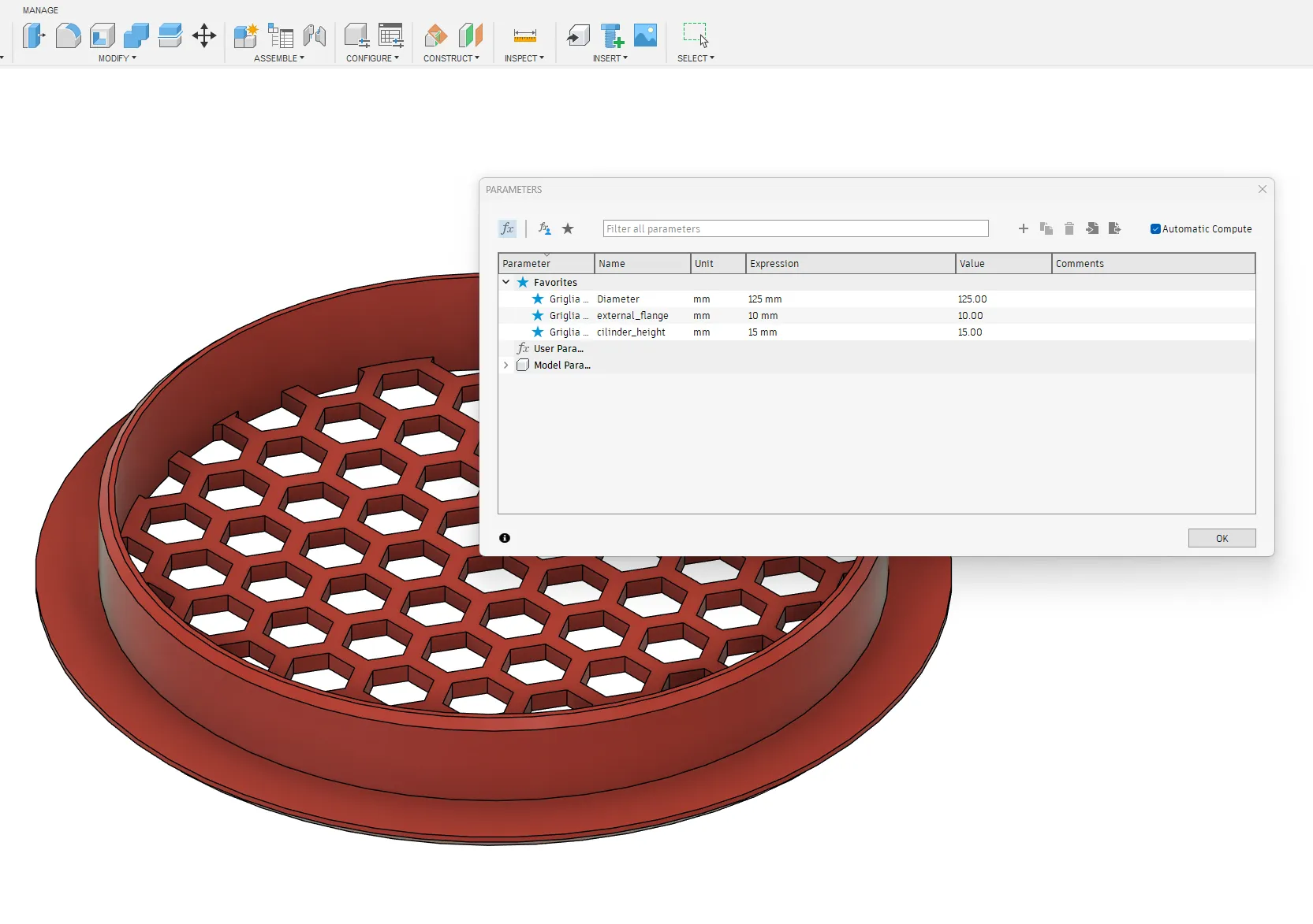
A powerful gaming PC generates a lot of heat, so effective ventilation is non-negotiable. This means creating clear pathways for cool air to enter (intake) and hot air to exit (exhaust). We'll do this by adding cutouts for fans and creating grills to cover them.

Action: Create a Fan Cutout and Grill
- Position the Fan: Decide where you want an exhaust fan (typically at the back or top of the case). Let's plan for a standard 120mm fan.
- Create the Cutout: On the appropriate panel, create a new sketch. Draw a
120mmcircle for the fan opening. Use theExtrudetool with the Cut operation to create the hole. - Design a Simple Grill: We'll create a basic slot grill.
- Create another sketch on the same panel face.
- Draw a single long, thin rectangle that crosses the fan opening. A width of
5mmis a good start. - Use the Create > Rectangular Pattern tool (which you've used before for 2D sketches) to duplicate this slot across the entire fan opening. Adjust the spacing to be visually appealing and not too restrictive for airflow.
- Use
Extrude (Cut)to cut these slots through the panel.
4. Keep it Tidy: Cable Routing
Effective cable management is key to good airflow and a professional-looking build. This means creating strategic openings to pass cables from the PSU to the motherboard, drives, and other components, keeping them out of sight.
Action: Create Cable Passthrough Holes
- Identify Pathways: Look at your component layout. Where do cables need to go? A large opening near the PSU and several smaller openings around the
Motherboard_Placeholderare common. - Sketch and Cut: On the appropriate panels, sketch a few rectangles or "stadium" shapes (rectangles with rounded ends).
- Extrude (Cut): Use the
Extrudetool to cut these shapes through the panels. You can add aFilletto the sharp edges to prevent cable snagging and give a more finished look.
For more granular cable control, you can design and 3D print custom cable clips.
3D Printed Cable Clips with Fusion 360
Modeling a fully parametric cable clip is a great mini-project. While we won't do it in this lesson, this tutorial from Product Design Online provides excellent step-by-step instructions for when you're ready to tackle it.
You don't need to read this now, but bookmark it. Skim through the 'Transcript' section to see the workflow: it involves using parameters, surface extrudes, and the thicken command—a powerful alternative to the solid extrude workflow.
Conclusion
Fantastic work. You have now added a significant layer of functional detail to your capstone project. By moving from a simple frame to a feature-rich enclosure, you are well on your way to creating a truly custom piece of hardware.
Key Takeaways:
- Plan with Placeholders: Always start by modeling or importing simple representations of your real-world components to ensure everything fits.
- Design for Function: Features like motherboard standoffs have standard dimensions and specific design requirements for strength and purpose.
- Ventilation is Critical: PC compartments need clear intake and exhaust paths. Fan cutouts and grills are essential design elements.
- Cable Routing is Design: Thoughtful cable passthrough holes are not an afterthought; they are a key part of a clean and functional design.
Next Lesson Preview:
You've just created several large cutouts in your desk's structural panels. How does this affect the overall strength? In our next lesson, we will begin to answer that question as we move into the analysis phase. You will learn how to apply materials to your components and perform a basic static stress analysis to identify potential weak points in your design.