Hello! Welcome back to the next stage of your capstone project.
In our last lesson, you successfully modeled the main structural parts of your desk—the Desktop and two Side_Panels—as separate, parametric components. They are currently positioned correctly in your design, but if you were to click and drag one, you'd see it moves independently. They are like pieces of wood cut to size and laid out, but not yet fastened together.
Today's goal is to perform that virtual assembly. Our learning outcome is to assemble the desk frame using joints and verify the design updates correctly when parameters change. We will lock these components together and then test the parametric "intelligence" of our design to ensure it behaves as a single, adaptable unit.
1. The Anchor: Grounding a Component
Before we start joining parts, we need to fix one component in space. This acts as an immovable anchor to which all other parts are attached, preventing the entire assembly from floating around. For our desk, the most logical anchor is the Desktop. This process is called Grounding.
Day 23 of Learn Fusion 360 in 30 Days for Complete Beginners!
To understand the concept of grounding and why it's the first step in creating an assembly, please read this brief section from a Product Design Online tutorial.
In the article, find the transcript section. Start reading from the heading 'When starting a new assembly...' and continue to the end of the section that describes the red thumbtack icon. This will explain the purpose and process of grounding.
Now, let's apply this to your desk model:
- Open your "Gaming Desk Capstone" file in Fusion 360.
- In the Browser tree on the left, find your
Desktopcomponent. - Right-click on the
Desktopcomponent. - From the context menu, select Ground.
You will see a small red thumbtack icon appear next to the Desktop component in the Browser. If you try to click and drag the desktop in the viewport, it will not move. It is now fixed.
2. Virtual Fasteners: Assembling with As-Built Joints
With our anchor in place, we can now connect the side panels. In Fusion 360, these connections are defined by Joints. Joints define the position and relative motion between components. Since your desk frame is a static structure, we will use a Rigid Joint, which removes all 6 degrees of freedom, simulating a glued or screwed connection.
There are two main commands for creating joints: Joint and As-Built Joint. Because we used a "top-down" design method where all our parts were modeled in their final positions, the As-Built Joint is the correct tool for the job.
Day 23 of Learn Fusion 360 in 30 Days for Complete Beginners!
This next section of the same article clearly explains the critical difference between the 'Joint' and 'As-Built Joint' commands.
Read the section starting just below the first image, from 'Under the Assemble dropdown list...'. Focus on understanding why 'As-Built Joint' is recommended for parts that are already in their final location.
Let's now rigidly join the side panels to the desktop.
To Join the Left Side Panel:
- From the main toolbar, go to Assemble > As-Built Joint. You can also use the shortcut Shift + J.
- In the "As-Built Joint" dialog box, ensure the Motion type is set to Rigid. The icon looks like two blocks fused together.
- For Components, you need to select the two components you want to join. Click on the
Side_Panel_Leftand then click on theDesktop. Their names will appear in the dialog. - Next, you need to define a Snap point. This is the common reference point that defines the joint's position. Any shared corner between the two components is a good, stable choice. Hover your cursor near the corner where the top of the side panel meets the underside of the desktop until a white joint origin symbol appears, then click to select it.
- Fusion 360 will play a quick "shake" animation to confirm the rigid connection. Click OK.
In the Browser, you will now see a Joints folder containing your new Rigid joint.
To Join the Right Side Panel:
Repeat the exact same process for the Side_Panel_Right:
- Activate the As-Built Joint tool again (Shift + J).
- Ensure Motion is Rigid.
- Select the
Side_Panel_Rightand theDesktopcomponents. - Select a shared corner as the Snap point.
- Click OK.
Your desk frame is now fully assembled. If you try to drag the side panels, they will not move, as they are now rigidly locked to the grounded desktop.
3. The Payoff: Verifying the Parametric Design
This is the moment where the power of your parametric setup becomes truly apparent. A well-built parametric model should update predictably when its driving parameters change. Regularly testing this is a crucial best practice.
Parametric Furniture Design With Autodesk Fusion
This article from the Autodesk blog reinforces the importance of this step. It's not just about building the model, but ensuring it's robust and adaptable.
Read the short section titled 'Best practices for parametric furniture design,' paying special attention to the point on 'Test and validate.' This is exactly what we are about to do.
Let's test your assembled desk frame.
- Go to the main toolbar and select Modify > Change Parameters.
- In the dialog box, find your user parameters:
DeskWidth,DeskDepth, andDeskHeight. - Change the value for
DeskWidth. For example, if it's 1500mm, change it to1200mm. Press Enter.
Observe the model. The desktop should shrink in width, and importantly, the Side_Panel_Right should move with it, maintaining its position at the edge. The As-Built Joint ensures the connection holds.
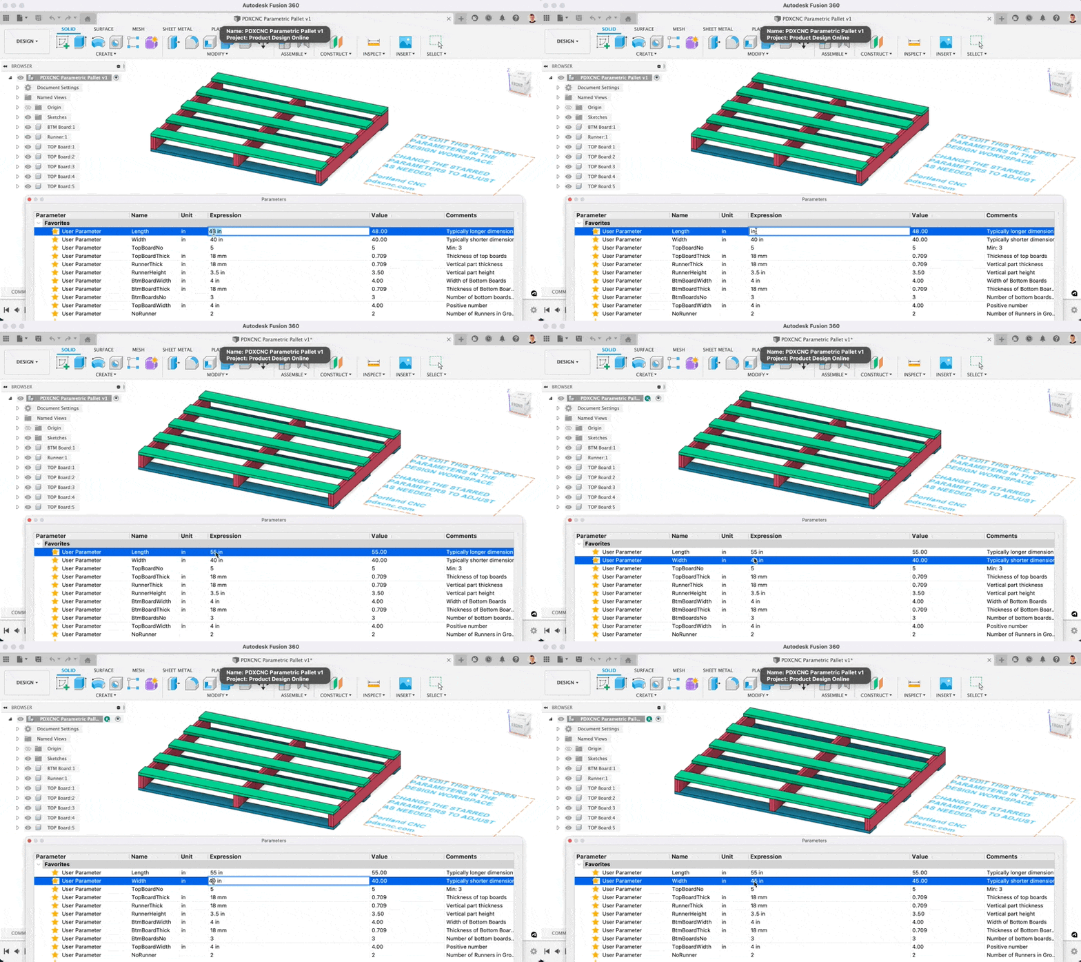
Now, continue testing:
- Change
DeskDepth(e.g., from 700mm to 800mm). The entire frame should get deeper. - Change
DeskHeight(e.g., from 750mm to 720mm). The side panels should shorten correctly, because their extrusion distance is defined by the formulaDeskHeight - MaterialThickness. The overall height will be exactly what you enter.
This ability to resize a fully assembled model by changing a few key numbers is the core benefit of this workflow. It allows for rapid iteration and customization, which is invaluable for your DIY projects.
360 Live: Fusion 360 and Furniture Design: Parameters for Production
To see a fantastic real-world example of this principle in action, watch this segment on designing a parametric bookcase. The presenter frequently tests his parameters to ensure the entire assembly updates correctly.
Watch the video from 38:50 to 41:13. Notice how after modeling the sides and back, he immediately goes to the parameters dialog and changes the width, depth, and shelf count, confirming that the entire model behaves as expected. This is the validation step we've just performed.
Conclusion
Excellent work. You have now transformed your collection of individual parts into a truly intelligent, unified assembly.
Key Takeaways:
- Grounding is the essential first step to creating a stable assembly by fixing one component in space.
- As-Built Joints are the right tool for connecting components that have been designed in their final positions.
- A Rigid Joint is used to create a static connection, like glue or screws, by removing all relative motion.
- Verification is key: The true test of a parametric assembly is changing the user parameters and confirming that the model updates predictably and without errors.
You have now built a robust, parametric frame. This solid foundation is ready for the next level of detail.
Next Lesson Preview:
With the main structure complete and behaving correctly, we can start designing the features that make this a custom gaming desk. In the next lesson, we will begin to design the PC compartment, using subtractive modeling techniques to create space and add features for mounting, ventilation, and cable routing.