Hello! Welcome back to your capstone project.
In the last lesson, you established the parametric heart of your desk design by creating user parameters for its primary dimensions: DeskWidth, DeskDepth, DeskHeight, and MaterialThickness. You then created a simple 2D sketch driven by these parameters.
Today, we'll transform that 2D sketch into a 3D structure. The learning outcome for this lesson is to model the main structural components as separate, parametric parts. We will build the desktop and the main side supports, ensuring each is an independent, intelligent "part" within our design file. This step is critical for organizing your project and preparing it for assembly in the next lesson.

1. The Building Blocks: Bodies vs. Components
So far, most of our 3D modeling has created "Bodies." A Body is simply a 3D shape. For a complex project like your desk, which will be made of multiple pieces of wood and 3D printed parts, we need something more powerful: Components.
Think of it this way:
- A Body is like a lump of clay. It has a shape, but no real identity or ability to interact with other lumps.
- A Component is like a finished Lego brick. It's a distinct part with its own properties, origin, and—most importantly—the ability to connect to other bricks using joints.
For your desk project, every separate piece of wood will be its own component. This allows us to define how they are joined, create a parts list (Bill of Materials), and manage a complex design effectively.
Day 13 of Learn Fusion 360 in 30 Days
To understand the crucial role of components in Fusion 360, please read these sections from an article on Product Design Online. It explains the core concepts clearly.
In the article, find the transcript section. Read the paragraphs starting with 'Let’s start with some key terminology' to understand the definition of a Component. Then, read the section starting with 'If you’re not already convinced, here are some more reasons you should always be using components.' This will clarify why we are taking this approach.
As the article highlights, using components is essential for applying joints, assigning physical materials, and creating manufacturing documents. This leads to two unofficial but widely followed "rules" in Fusion 360:
- Rule #1: Start your design with a component. (We'll see how to do this in a moment).
- Rule #2: Always give your components, bodies, and sketches meaningful names.
2. The "Top-Down" Assembly Workflow
We will build your desk using a "top-down" assembly method. This means we will design all our components within the context of a single master design file—the "Gaming Desk Capstone.f3d" file you created. This is like building the desk in a virtual workshop, cutting and shaping each piece in place relative to the others.
The workflow for creating each structural part will be:
- Create a sketch for the part's profile.
- Use the Extrude command to give it thickness.
- In the Extrude dialog, set the "Operation" to New Component.
This process creates a 3D part that is immediately a component, ready for assembly.
3. Hands-On: Modeling the Desktop
Let's start with the largest component: the desktop.
- Open your "Gaming Desk Capstone" file. You should see the rectangular sketch you created in the last lesson.
- Press 'E' to activate the Extrude tool.
- Select the sketch profile.
- For the "Distance," don't type a number. Instead, enter your parameter name:
MaterialThickness. - In the Extrude dialog, find the Operation dropdown menu. Change it from the default "New Body" to "New Component".
- Click OK.
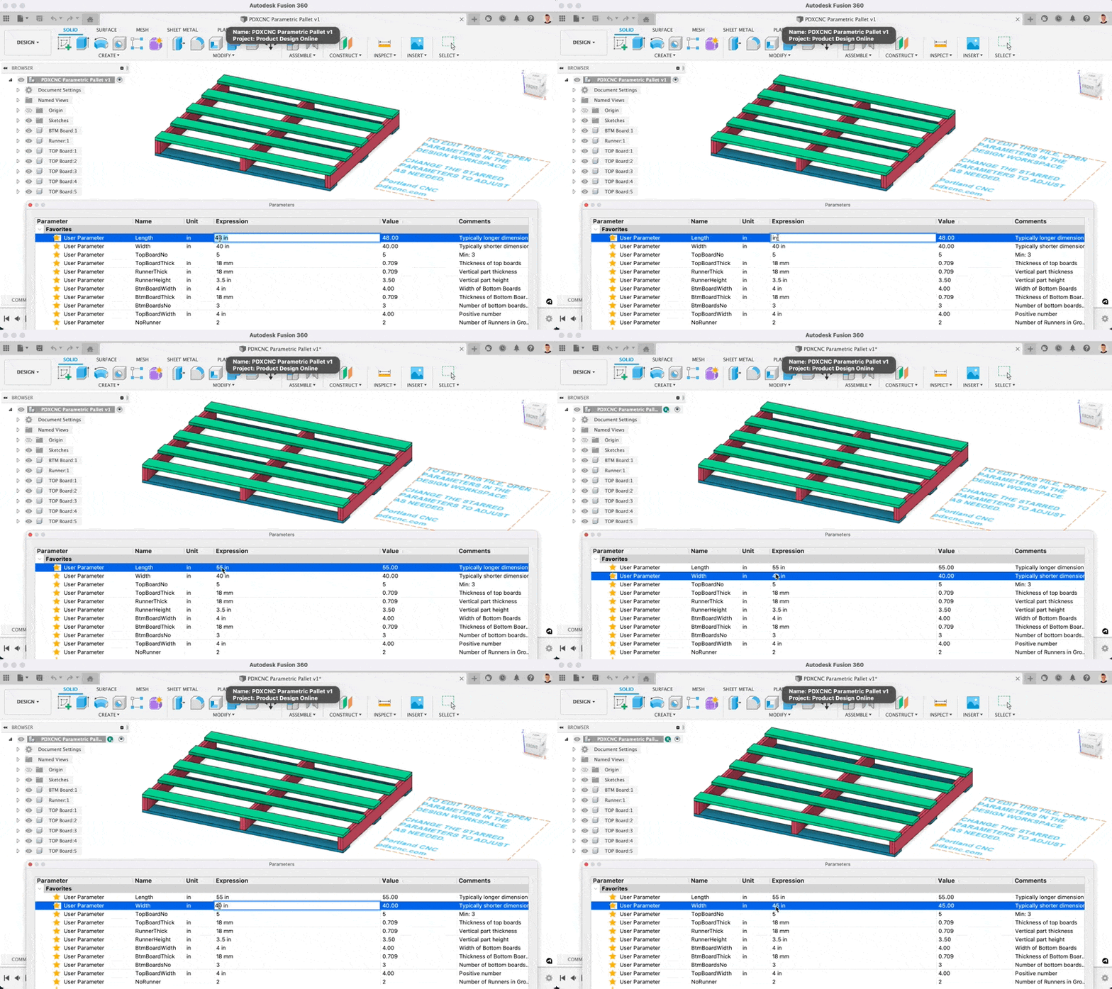
Now, look at the Browser on the left side of your screen. You'll see you no longer just have a "Bodies" folder. You have a new Component (likely named Component1:1). This is your desktop! Follow Rule #2: right-click on it and rename it to Desktop.
4. Modeling the Side Panels
Now we'll create the two vertical side panels that will support the desktop. We'll follow a process demonstrated perfectly in the context of building a bookcase.
Fusion 360 for Woodworkers - Lesson 2 Parametric modelling, bodies and components
This video from 'The Woodgrafter' shows the exact workflow we'll use to create the side panels. He is building a bookcase, but the principle of sketching on an existing face and extruding a new component is identical.
Watch the segment from 18:42 to 20:47. Pay close attention to how he sketches the side panels on the base, extrudes them, and selects 'New Component' in the dialog.
Let's apply that process to your desk:
- Use the View Cube or orbit controls to look at the underside of your
Desktopcomponent. - Create a New Sketch and select the bottom face of the desktop as the sketch plane.
- Draw two rectangles for the side panels.
- Use the 2-Point Rectangle tool.
- Anchor one corner of the first rectangle to the front-left corner of the desktop. Make its depth
DeskDepthand its widthMaterialThickness. - Anchor the second rectangle to the front-right corner. Make its depth
DeskDepthand its widthMaterialThickness. - Your sketch should be fully constrained (black lines).
- Click Finish Sketch.
- Press 'E' for the Extrude tool and select both rectangular profiles you just drew.
- Start pulling the arrows downward, away from the desktop.
Correcting the Height with a Formula
Now for a critical step. Our DeskHeight parameter represents the total height from the floor to the top of the desk. Since we've already used MaterialThickness for the desktop, we need to subtract that from the height of the legs.
For the extrusion "Distance," enter the formula: DeskHeight - MaterialThickness
This ensures that no matter what material thickness you choose later, the overall desk height remains correct. This is the power of parametric modeling.
Fusion 360 for Woodworkers - Lesson 2 Parametric modelling, bodies and components
The video you watched earlier contains a perfect explanation of this exact problem and solution. The creator initially makes the side panels too tall and then shows how to use a formula to fix it.
Watch from 22:30 to 24:30. This segment demonstrates precisely why we use a formula (bookcase height - stock thickness) to get the correct final dimension.
- Finally, in the Extrude dialog, ensure the Operation is set to "New Component".
- Click OK.
In your Browser, you will now see two new components. Rename them Side_Panel_Left and Side_Panel_Right.
Conclusion
Fantastic work! You have successfully modeled the primary structure of your desk. By doing so, you've put several key concepts into practice.
Key Takeaways:
- Components are essential: For any multi-part design, you must use Components, not just Bodies, to enable assembly, motion (joints), and manufacturing documentation.
- Top-Down Modeling is efficient: Creating components in the context of the main assembly allows you to use existing geometry for reference, ensuring everything fits together.
- "New Component" is key: The "New Component" option in the Extrude tool is the most direct way to create parts in a top-down workflow.
- Parametric formulas are powerful: Using mathematical expressions like
DeskHeight - MaterialThicknesscreates robust relationships in your model, making it truly adaptable to change.
If you look at your Browser tree now, you should see your main design file containing three distinct components: Desktop, Side_Panel_Left, and Side_Panel_Right. You have successfully achieved today's learning outcome.
Next Lesson Preview:
You now have the virtual "pieces of wood" for your desk. In the next lesson, we will begin the assembly process. You will learn how to use Joints to define the rigid connections between these components, locking them together just as screws or glue would in the real world.