Hello and welcome to the first lesson in our new module, Advanced Modeling & Design Refinement.
In the previous modules, you've built a fantastic foundation. You've gone from a blank canvas in Fusion 360 to designing, printing, iterating, and finishing a complete functional part. This means you now understand the entire workflow from concept to physical object.
Now, we're going to circle back to Fusion 360 and add some powerful tools to your design arsenal. These tools will allow you to break free from simple, boxy shapes and start creating the more complex and organic designs needed for your gaming accessories and custom desk project.
Today's Goal: Your learning outcome is to create and use construction planes and axes for off-grid geometry.
So far, most of your sketches have started on one of the three default origin planes (XY, YZ, XZ) or a flat face of your model. But what if you need to add a feature at a specific angle, or on a curved surface? That's where construction geometry comes in. These are custom planes and axes that you create to serve as a reference for your sketches and features, allowing you to model with far greater freedom and precision.
1. Understanding Construction Planes
Construction planes are temporary, user-defined flat surfaces that you can place anywhere in your 3D space. Think of them as portable sketchpads. You can find all the tools for creating construction geometry under the Construct menu in the Design workspace.
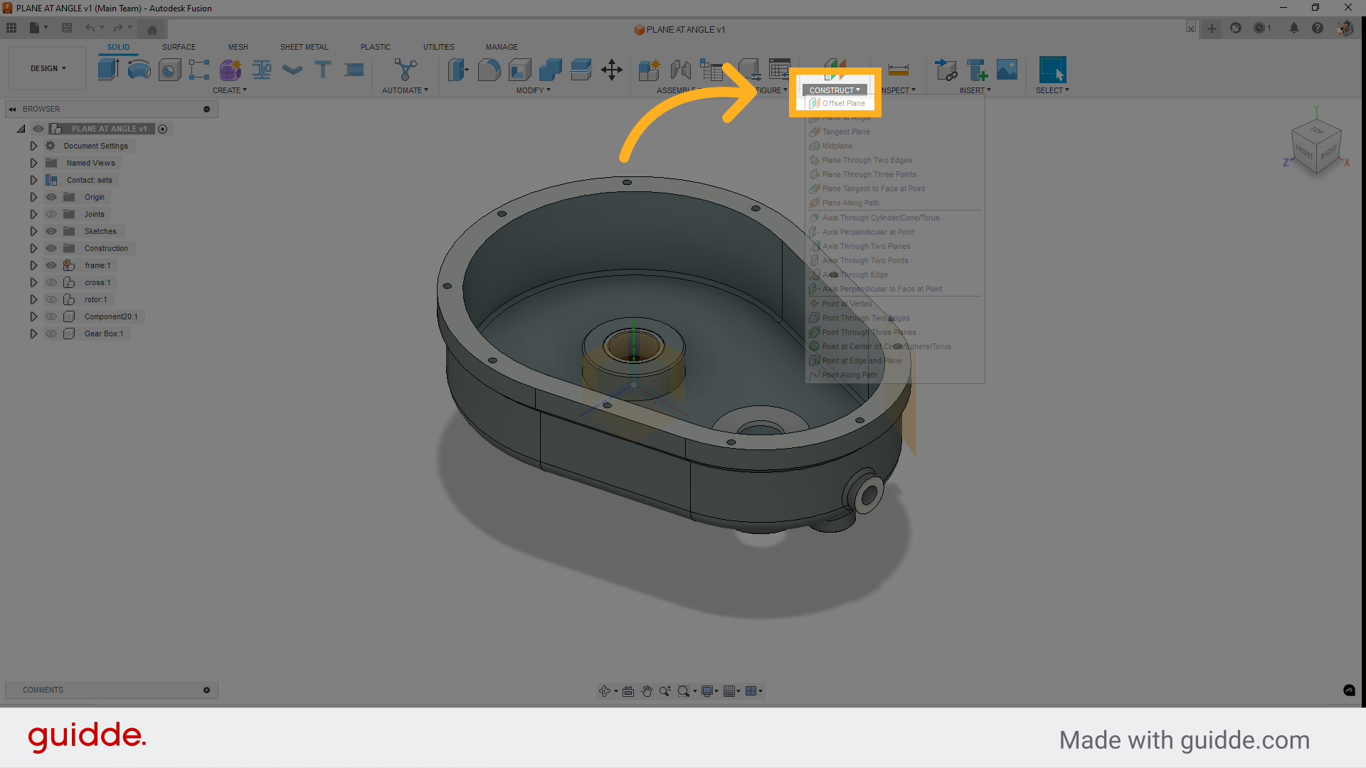
There are many ways to create planes, but we'll focus on the four most common and versatile types.
To get a solid overview, let's watch some segments from a detailed tutorial.
Episode 13, Construction Planes
This video from Brad Tallis provides a thorough walk-through of the construction menu. We'll start with the most fundamental tool: the Offset Plane.
Watch from 4:02 to 5:20. This segment demonstrates the Offset Plane, which creates a new plane parallel to an existing face or plane at a specified distance.
The Workhorse Construction Planes:
-
Offset Plane: As you just saw, this is perfect for starting a sketch at a precise distance from an existing surface. For example, you could use it to model a shelf that needs to sit exactly 20mm below the top of a bracket.
-
Plane at Angle: This lets you create a plane that pivots around a selected edge or axis. It's essential for creating any feature that isn't at a 90 or 180-degree angle, like an angled leg for a monitor stand or a brace for a shelf.
-
Tangent Plane: This creates a plane that just touches a curved surface (like a cylinder or sphere) at a single point or line. This is your go-to tool when you need to add features onto a curved part, such as a mounting boss for your gaming headset holder on a cylindrical tube.
-
Midplane: This creates a plane exactly halfway between two other faces or planes. It is incredibly useful for ensuring symmetry. For instance, if you were designing a clamp, you could model one half and then use a midplane to perfectly mirror it to create the other half.
Let's watch the demonstrations for the other three key plane types.
Episode 13, Construction Planes
Continuing with the same video, let's see how the 'Plane at Angle', 'Tangent Plane', and 'Midplane' tools work.
Please watch the following segments: Plane at Angle (9:17 - 11:16): Notice how it requires a line or edge to define the angle. Tangent Plane (11:16 - 13:01): Pay attention to the 'Reference Plane' option, which gives you precise angular control on the curved surface. Midplane (13:56 - 16:03): Observe how it can be used for both parallel and angled faces.
2. The Role of Construction Axes
Sometimes, to create the plane you need, you first need to create a reference line in 3D space. This is where Construction Axes come in. An axis is an infinite line that can be used to define the position of a plane, act as a center for a Revolve or Circular Pattern, or define motion for a joint.
The most common use case is creating an axis through the center of a cylinder. This gives you a perfect centerline to work from.
Episode 13, Construction Planes
Let's return to the video to see how to create an axis and, more importantly, how to use that axis to help create a plane.
Watch from 23:07 to 25:14 and then from 26:54 to 27:53. The key takeaways are: How to create an Axis Through Cylinder to define the center of a circular part. How you can then use that newly created axis as the reference line for a Plane at Angle, allowing you to slice a plane right through the center of the cylinder at any angle you desire.
This demonstrates the core concept of advanced modeling: often, you must create one piece of construction geometry to serve as a reference for another. You build up your references step-by-step to place a feature exactly where you want it.
3. Your Turn: Modeling an Angled Feature
Now, let's put this into practice by modeling a feature that would be impossible without construction geometry: an angled pipe joining a cylinder. This exercise will require you to combine multiple tools, just as we discussed.
We will follow the excellent practical example at the end of the video you've been watching.
Episode 13, Construction Planes
Watch this final segment which walks through a real-world design scenario. The goal is to add a cylindrical boss to a larger cylinder, but at a specific angle.
Watch from 39:04 to 46:27. Follow along with the presenter as he troubleshoots his way to the solution. Notice that to create the angled plane, he first has to create a simple 2D sketch with a construction line to serve as the axis for his 'Plane at Angle' tool.
Follow these steps in Fusion 360 to recreate the model:
- Create the Base: Start a new design. Create a cylinder on the origin. A diameter of 80mm and a height of 100mm is a good start.
- Create the Reference Line:
- Create a new sketch on one of the origin planes that cuts through the center of your cylinder (e.g., the XZ plane).
- Use the
Linetool to draw a line at an angle. This line does not need to touch the cylinder. It will only serve as a directional reference. - Select the line and change its
LinetypetoConstructionin the Sketch Palette. This tells Fusion it's a reference line, not part of a profile to be extruded. - Finish the sketch.
- Create the Angled Plane:
- Go to
Construct > Plane at Angle. - For the
Line, select the construction line you just drew. - You can now set the angle of the plane. Let's use -25 degrees as shown in the video.
- Go to
- Model the Angled Pipe:
- Create a new sketch on the new angled construction plane.
- Draw a circle for the pipe's profile (e.g., 30mm diameter). Position it so it will intersect the main cylinder.
- Finish the sketch.
- Use the
Extrudetool on the circle profile. - Change the
Extent Typeto To Object. - Select the face of the main cylinder as the object.
- Ensure the
Operationis set to Join. Click OK.
You have now successfully created geometry that is "off-grid" and at a complex angle relative to your base part. This is a fundamental skill for advanced design.
4. A Reference for the Future
We've covered the most essential construction tools, but there are many others for more specific situations (Plane Through Three Points, Plane Along Path, etc.). You don't need to memorize them all now, but it's good to know they exist.
Create Construction Planes and Axes - Autodesk
The document below from Autodesk serves as a great reference guide. I suggest bookmarking it. You don't need to read it now, but if you ever wonder 'How can I create a plane that does X?', this guide will likely have the answer.
Briefly skim through this PDF. Notice how it's structured with clear headings for each tool, like 'Plane at Angle' or 'Axis Through Cylinder/Cone/Torus'. It's a handy cheat sheet for the entire Construct menu.
Conclusion
In this lesson, you've taken a major step into advanced modeling. You've learned how to break away from the default planes and create features anywhere in 3D space.
Key Takeaways:
- Construction geometry (planes and axes) allows you to create sketches and features that are not aligned with the origin or existing flat faces.
- The four most common plane types are Offset, Plane at Angle, Tangent, and Midplane.
- Construction Axes are reference lines often used to help define the position and orientation of construction planes.
- Complex modeling often requires combining tools: creating one piece of reference geometry (like an axis or a sketch line) to define the next.
Next Lesson Preview:
In our next lesson, we will learn how to create complex shapes along a custom path using the Sweep operation. This is perfect for creating things like custom cable routing channels, ergonomic grips, or decorative flourishes. You will see that the Plane Along Path tool, one of the construction tools we briefly mentioned today, is the key to creating the profile that a Sweep follows.