Hello! Welcome back to your course on mechanical design.
In our last lesson, you successfully built your first fully parametric model: a simple box whose dimensions were controlled by user parameters. You learned how to define those parameters and apply them to sketches and 3D features.
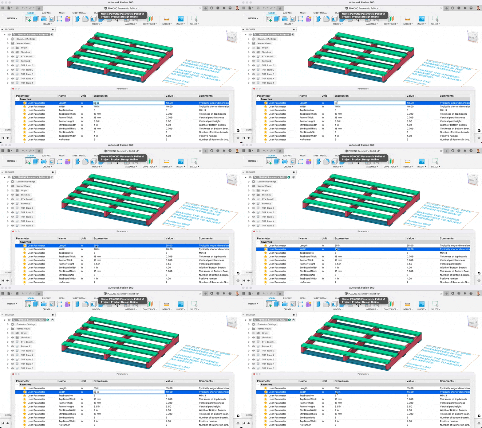
Today, we'll focus on the "payoff" of that work. The learning outcome for this lesson is to demonstrate how changing a parameter value automatically updates the 3D model. We'll explore why this happens and witness the incredible efficiency it brings to the design process. This principle is the key to rapidly iterating and refining your designs, from simple 3D prints to your eventual custom desk project.
Let's start with a quick visual of this principle in action.
1. The Core Principle: From Static Numbers to Live Formulas
In the previous lesson, you created a box using parameters like box_width and box_height. When you change the value of box_width from 100mm to 150mm, the 3D model updates instantly. Why?
Because you are no longer designing with static numbers. You are creating a "recipe" where the dimensions are linked to the names of your parameters. The model doesn't know its width is 100mm; it only knows its width is box_width. When you update the value associated with that name, Fusion 360 simply re-runs the entire recipe (your design timeline) with the new value.
This is analogous to a financial spreadsheet. If you have a cell for "Revenue" and another for "Expenses," you can create a third cell, "Profit," with the formula =Revenue - Expenses. If you update the Revenue number, the Profit cell updates automatically because it's linked by a formula, not a static value. Parametric modeling applies this same powerful logic to geometry.
2. Hands-On: Exploring Dynamic Updates
Let's put this into practice. Open the parametric box file you created in the last lesson. We're going to modify it to see this principle in a more powerful way.
Step 1: The Basic Update
- Go to Modify > Change Parameters.
- Change the value for
box_widthorbox_height. - Click out of the field or press Enter, and watch your model resize in the background.
This is the fundamental demonstration you saw at the end of the last lesson. Now, let's add a layer of intelligence.
Step 2: Adding a Dependent Parameter
What if we want one dimension to always be based on another? For example, let's say we want the fillet on the corners of our box to have a radius that is always 1.5 times the wall thickness.
- In the Change Parameters dialog, click the
+User Parameter button. - Create a new parameter with the following properties:
- Name:
corner_radius - Expression:
wall_thickness * 1.5
- Name:
- Notice that Fusion 360 automatically calculates the value. If your
wall_thicknessis3mm, the value forcorner_radiuswill show4.5mm. Click OK.
Step 3: Applying the New Parameter
Now, let's apply this new, dependent parameter to our model.
- Activate the Fillet tool (
Modify > Fillet). - Select the four outer vertical edges of your box.
- In the
Radiusfield of the Fillet dialog, instead of typing a number, type the parameter name:corner_radius. - Click OK. The fillets are applied.
Step 4: The Demonstration
This is the key moment. Go back to Modify > Change Parameters.
Now, change the value of wall_thickness to 5mm.
Observe your model closely. Two things should happen simultaneously:
- The walls of the box will become thicker (as controlled by the Shell feature).
- The corner fillets will become larger (as controlled by the Fillet feature).
You changed only one value, but because corner_radius was defined as wall_thickness * 1.5, both features updated together. This is the essence of building "design intent" into your model. You've created a rule that the corners should scale with the wall thickness, and Fusion 360 enforces it for you automatically.
3. Watching a Pro: Parametric Design in a Project
Let's see how these concepts are used in a slightly more complex project. The following video demonstrates the creation of a parametric bookshelf. Since your goals include woodworking for your custom desk, this example should be particularly relevant. We'll focus on the part where parameters with equations are used and then adjusted.
Getting Started with Fusion 360 Part 3 - SMART MODELS with Parameters!
The 'Getting Started with Fusion 360 Part 3' video from The Fusion Essentials provides an excellent demonstration of building a parametric bookshelf. Pay close attention to how a mathematical expression is used to position a part and how the entire model updates when parameters are changed.
Watch from 05:01 to 08:04 to see how a parameter is used in a mathematical equation to correctly position the second side of the shelf. Then, watch the final wrap-up from 13:39 to 14:21 to see the satisfying result of changing multiple parameters and watching the entire shelf assembly update in real time.
The key idea from the video is that you can use parameters not just for dimensions, but for positions, quantities in a pattern, and in formulas that drive other features (shelf_width - shelf_thickness).
4. Your Turn: A Practical Challenge
Now, let's use your parametric box for a practical design task.
Goal: Modify your box to become a holder for a standard 9V battery.
- A typical 9V battery has approximate dimensions of: Length: 48.5mm, Width: 26.5mm, Height: 17.5mm.
Your Task:
- Open the Change Parameters dialog for your box.
- Adjust your
box_depth,box_width, andbox_heightparameters to create an enclosure that would snugly fit the battery. Remember to add a little extra clearance (e.g., 0.5mm to 1mm on each side) so the battery isn't too tight. - You might also want to adjust the
wall_thicknessto something appropriate for a small plastic case, perhaps2mm. - Observe how the
corner_radiusupdates automatically when you change the wall thickness.
This exercise directly mirrors a real-world workflow: taking measurements of an object and designing a part to interface with it. By simply changing a few values in a table, you have completely repurposed your design in seconds—a task that would have required significant redrawing in a non-parametric system.
Conclusion
In this lesson, you truly experienced the power of parametric design. You saw firsthand how a well-structured model with user parameters can be modified instantly and reliably.
Key Takeaways:
- Changing a parameter's value in the Change Parameters dialog automatically updates any sketch dimension or feature that references it.
- You can create dependent parameters that are defined by formulas using other parameters (e.g.,
corner_radius = wall_thickness * 1.5). - This approach allows you to build "design intent" into your models, creating robust relationships between different geometric features.
- The ability to quickly change dimensions makes iterating on designs and creating custom-fit parts incredibly efficient.
You have now completed the module on Parametric Design Principles. You've mastered how to create intelligent, adaptable single parts. However, most products are not single parts; they are assemblies of many components working together.
In the next module, Multi-Component Design: Assemblies & Joints, we will start by exploring the critical difference between Bodies and Components. This is the foundational concept for building complex assemblies, and it will be essential as you progress towards designing multi-part projects like your custom gaming desk.