Hello! Welcome back to your journey into Fusion 360.
In our last few lessons, we've built a strong foundation. You learned how to define parameters to capture design intent and how to expertly manipulate the Design History Timeline to edit, suppress, and reorder the "recipe" of your model.
Today, we're going to combine those skills to achieve a core principle of modern CAD: full parametric control. The learning outcome for this lesson is to create a simple parametric box whose dimensions are controlled by user parameters. We'll build a 3D model where you can change its length, width, or height by simply editing a value in a table, and the entire model will update automatically. This technique is incredibly powerful and will be essential for iterating on your designs, from simple gaming accessories to your ultimate goal of a custom PC desk.
1. What is Parametric Modeling?
At its heart, parametric modeling is about creating smart, flexible designs. Instead of using fixed, "hard-coded" numbers for dimensions, you use named variables, or parameters.
Let's start with a quick reading to formalize this concept.
Parametric Modelling in Autodesk Fusion 360 – Making a Box
The article 'Parametric Modelling in Autodesk Fusion 360' from Norwegian Creations gives a perfect, concise definition of what we're about to do.
Please read the introductory section titled 'What is Parametric Modelling?'. It clearly explains the core idea and its benefits.
As the article states, when you change a parameter, "the model will then change accordingly while still keeping its integrity intact." This is the magic we're going to create today.
2. Hands-On: Building Your Parametric Box
We will now build a simple box from scratch, but this time, every key dimension will be driven by a user-defined parameter. The best way to learn this is by doing, so fire up Fusion 360 and let's get started.
We'll be following a workflow demonstrated in the video below. I'll break it down step-by-step, asking you to watch a specific segment and then perform the action yourself.
Intro to User Parameters and Joints | Day 19 of Learn Fusion 360 in 30 Days - 2023 EDITION
This video from Product Design Online provides a clear, end-to-end demonstration of creating a parametric box. We'll use it as our guide.
You don't need to watch the whole video at once. I will point you to specific short segments as we go through the steps below.
Step 1: Define Your Parameters
First, we need to create the named variables that will control our box.
- Watch: The segment from 00:25 to 01:26 in the video, where new user parameters are created.
Now, it's your turn.
- In Fusion 360, go to the Modify menu and select Change Parameters.
- In the Parameters dialog, click the
+User Parameter button. - Create the following four parameters. Note that names cannot have spaces. Using an underscore
_or camelCase likeboxWidthis common practice.
| Name | Expression (Value) | Comment |
|---|---|---|
box_width |
100mm |
Overall width of the box |
box_depth |
80mm |
Overall depth of the box |
box_height |
50mm |
Overall height of the box |
wall_thickness |
3mm |
Thickness of the walls |
Your dialog should look something like this:
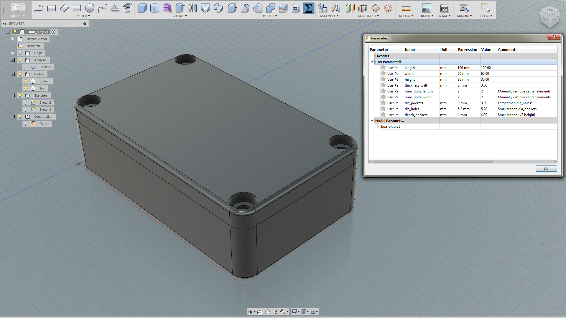
Step 2: Create the Base Sketch
With our parameters defined, we can now use them in a sketch.
- Watch: The video segment from 01:26 to 02:11, which shows how to apply parameters to a rectangle's dimensions.
Let's apply that.
- Close the Parameters dialog.
- Create a New Component and name it
Parametric Box. - Create a New Sketch on the bottom (XY) origin plane.
- Select the Center Rectangle tool and start it from the origin.
- As you define the rectangle's dimensions, instead of typing a number, start typing the name of your parameter. For the vertical dimension, type
box_depth. For the horizontal dimension, typebox_width. Fusion 360 will autocomplete the name for you. - Press
Enter. Your sketch should now be fully constrained, with the dimension values showingfx: 100andfx: 80. Thefxindicates the dimension is driven by a function or parameter.
Step 3: Extrude and Shell the Body
Now we'll turn our 2D sketch into a 3D hollow box, using our remaining parameters.
- Watch: The video segment from 02:11 to 03:16. This demonstrates using a parameter for the extrude distance and then creating another parameter "on the fly" for the shell thickness.
Follow these steps:
- Finish Sketch.
- Select the Extrude tool and click on your sketch profile.
- In the
Distancefield of the Extrude dialog, typebox_height. The extrusion distance will immediately update to 50mm. Click OK. - Activate the Shell tool from the
Modifymenu. - Select the top face of the box.
- In the
Inside Thicknessfield, typewall_thickness. The value will update to 3mm. Click OK.
You now have a complete 3D box where every critical dimension is linked to your user parameters.
3. The Payoff: Witnessing Parametric Control
This is the moment where the power of this approach becomes clear.
- Watch: The final segment of the video, from 03:16 to 03:54, shows how changing a parameter value instantly updates the 3D model.
Let's test your model.
- Go back to Modify > Change Parameters.
- In the dialog box, change the expression for
box_widthfrom100mmto150mm. - Press
Enterand observe your 3D model in the background. It should instantly get wider. - Now, change
box_heightto30mmandwall_thicknessto5mm. - Watch as the model updates flawlessly with each change.
Feel free to experiment with different values. This is the core of parametric design: you have separated the design intent (the box has a width, a height, and a wall thickness) from the specific dimensions, making your model robust and easy to modify.
Conclusion
In this lesson, you successfully created a fully parametric box. You have now bridged the gap between defining parameters and seeing them drive a 3D model in real-time.
Key Takeaways:
- User Parameters are named variables you create to control your design's dimensions.
- The Change Parameters dialog (
Modify > Change Parameters) is the central hub for managing these variables. - You can apply parameters to any input field, such as sketch dimensions, extrusion distances, or shell thicknesses, by simply typing the parameter's name.
- Changing a parameter's value in the dialog automatically updates every feature in the model that references it.
You've now mastered the fundamental skills for creating single, intelligent parts. However, most real-world products are assemblies of many parts. In our next module, we'll dive into multi-component design. You'll learn the crucial difference between bodies and components, the building blocks of any complex assembly, preparing you to design objects with multiple interlocking pieces.