Hello! Welcome back.
In our last few lessons, we've focused on designing the geometry of individual parts to make them printable, covering overhangs, wall thickness, and bridging. Now, we'll shift our focus to a crucial aspect of creating functional objects: designing how separate parts fit together.
Today's lesson is about applying the correct clearances to create parts that assemble perfectly. You'll learn how to design for both slip-fits, where parts move freely, and press-fits, where they are held together by friction. This is fundamental for almost any multi-part project you'll tackle, from simple enclosures to your custom gaming desk.
1. The Theory: Tolerance, Clearance, and Fit
From your mechanical engineering background, you'll likely recall the concepts of tolerance and fit from the world of traditional manufacturing. In 3D printing, these concepts are just as critical, but the underlying causes and typical values are different.
- Tolerance is the unavoidable variation in a printed part's dimensions compared to the digital model. It's caused by factors like filament expansion/contraction, nozzle diameter, and tiny inaccuracies in the printer's motion system. Because of tolerance, a 10mm peg you design will not print at exactly 10.00mm.
- Clearance is the intentional space you design between two mating parts to compensate for tolerance and achieve a desired fit.
Let's watch a video that explains these concepts and introduces the three primary types of fit in the context of 3D printing.
Beginner's Guide to Fit and Tolerance in Fusion 360 - Get the Perfect Fit from Your 3D Printer / CNC
The video "Beginner's Guide to Fit and Tolerance in Fusion 360" by Practical Alchemy provides an excellent overview of why we need clearance and the different types of fit we can design.
Watch from the beginning to 08:25. The first part (up to 04:47) explains tolerance and tolerance stacking. The second part (04:47 to 08:25) details the three main types of fit: Interference (press-fit), Clearance (slip-fit), and Transition.
To summarize the video's key points:
- Interference Fit (Press-Fit): The "peg" is designed to be slightly larger than the "hole." This requires force to assemble and creates a strong, friction-based connection.
- Clearance Fit (Slip-Fit): There is a definite gap between the parts, allowing them to slide or rotate freely. Think of an axle in a wheel or a lid on a box.
- Transition Fit: The "in-between" state. Parts fit together snugly, with minimal free play and no force required for assembly. This is great for parts that need to be aligned before being secured with screws.
2. Finding Your Numbers: The Fit Test
So, how much clearance should you add? 0.2mm? 0.5mm? There is no single universal answer. The ideal clearance depends on your specific printer, the material you're using, and your slicer settings. The best way to find the right values is through empirical testing, which aligns with your preference for hands-on learning.
You can design and print a simple "fit block" or "tolerance gauge" to physically test how different clearances feel.

This next video segment demonstrates how to create such a test and use it to zero in on the precise values for your machine.
Beginner's Guide to Fit and Tolerance in Fusion 360 - Get the Perfect Fit from Your 3D Printer / CNC
Let's return to the Practical Alchemy video to see how to design and use a fit block to determine your printer's ideal clearances.
Watch the section from 08:25 to 13:17. This part walks through the process of creating a simple tolerance block in Fusion 360, printing it, and using it to find the values for a good clearance, transition, and interference fit.
The key takeaway is to start with a wide range of values (e.g., 0.2mm, 0.4mm, 0.6mm, 0.8mm) and then print a second, more refined test around the value that felt best. For most consumer FDM printers like the Bambu A1, a good starting point for a slip-fit clearance is often around 0.2mm to 0.5mm.
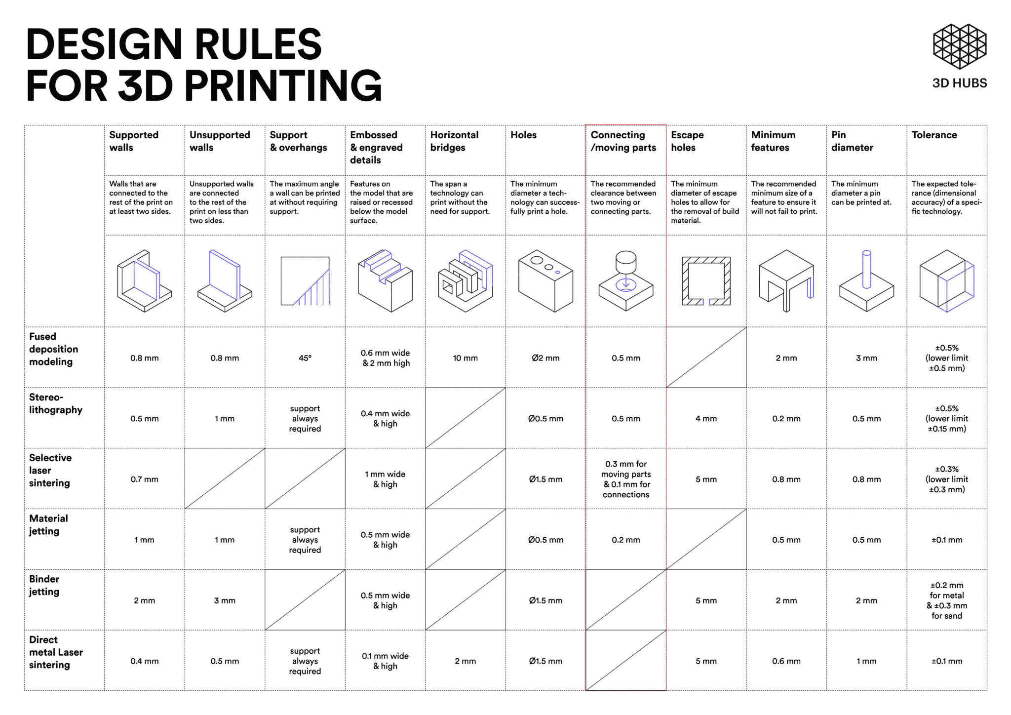
3. Applying Clearances in Fusion 360
Once you know your target clearance values, you need an efficient way to apply them in your designs. Let's look at the two best methods in Fusion 360.
Method 1: The Press Pull Command
For simple features like adding clearance to a screw hole, the Press Pull command (keyboard shortcut Q) is a quick and effective tool.
Method 2: Parametric Offset in a Sketch
For more complex parts or to maintain design flexibility, the best practice is to use a parametric approach. This involves:
- Defining your clearance values as User Parameters (e.g.,
slip_fit_clearance). - Projecting the geometry from one part into the sketch of the mating part.
- Using the
Offsettool with your user parameter to create the clearance.
This method is incredibly powerful. If you print a test part and find the fit is too tight, you only need to change the value in the parameters table, and your entire model will update automatically. Given your programming interest, you'll likely appreciate this systematic approach.
This video demonstrates both techniques clearly.
The Best Way to Add Tolerances in Fusion 360!
The video "The Best Way to Add Tolerances in Fusion 360!" by Joseph Willis offers a fantastic, practical demonstration of how to apply these concepts.
Please watch from 01:45 to 06:14, and then from 07:17 to 08:45. The first segment (01:45 - 02:54) shows the simple Press Pull method. The main segment (02:54 - 06:14) details the more robust parametric offset method, including how to create a user parameter on the fly. The final part (07:17 - 08:45) shows the tangible results of printing with 0.1mm vs 0.2mm clearance, reinforcing why testing is so important.
Special Case: Threads
Threads are a common feature where clearance is critical. Fusion 360 applies a very small default clearance, but it's rarely sufficient for the tolerances of FDM printers. You'll need to add more.
3D Printed Threads – Model Them in Fusion 360
The article "3D Printed Threads – Model Them in Fusion 360" from Product Design Online explains a specific technique for this.
Read the section titled "Creating Clearance in Fusion 360". This short section describes using the Offset Face command (Q) on the flanks of a modeled thread to add the necessary extra clearance. Note the distinction it makes between Clearance and Tolerance.
4. Your Turn: Design a Parametric Fit-Test
Now it's time to put this into practice. You will design a two-part assembly in Fusion 360 that you can print to test and calibrate clearances once your printer arrives.
Design Task:
-
Create User Parameters: In the
Modify > Change Parametersdialog, create two parameters:peg_diameter=10mmslip_clearance=0.4mm(This is the total clearance on the diameter)
-
Model the Base Plate:
- Create a base plate (e.g., 100mm x 40mm x 10mm).
- Create three holes through the plate, each with a diameter of
peg_diameter. - Hole 1 (Slip-Fit): Use the
Press Pullcommand to offset the inside face of the first hole. The offset value should beslip_clearance / 2. This creates the desired slip-fit gap. - Hole 2 (Press-Fit): Use
Press Pullto offset the second hole by-0.1mm. This will create a 0.2mm interference fit, which should require force to assemble. - Hole 3 (Nominal Fit): Leave the third hole at its nominal
peg_diameter. This will demonstrate why zero clearance doesn't work.
-
Model the Peg:
- Create a new component for the peg.
- Model a simple cylindrical peg with a diameter of
peg_diameterand a height of 20mm. Add a small handle or flange at the top to make it easy to grip.
When you're done, you'll have a model that's perfectly set up to test different fits. By trying the peg in each hole of the printed part, you'll physically feel the difference between a slip-fit, a press-fit, and a failed nominal fit.
Conclusion
You've now learned one of the most important skills in designing functional 3D printed parts. Understanding and applying clearance is the key to moving from single-body models to complex, multi-part assemblies that work as intended.
Key Takeaways:
- Tolerance is the unavoidable manufacturing error; Clearance is the intentional design gap to compensate for it.
- The three main fit types are Clearance (Slip-Fit), Interference (Press-Fit), and Transition Fit.
- The ideal clearance values are unique to your printer and material. You must print test pieces to find what works for you.
- In Fusion 360, you can use Press Pull for quick adjustments or a parametric sketch offset for robust, easily updatable designs.
In our next lesson, we'll address another practical challenge in 3D printing: what to do when a part is too big for your printer. You will learn how to split a large model into smaller, printable sections and design features to help reassemble them accurately.