Hello! Welcome back to our module on Design for Additive Manufacturing (DfAM).
In the last lesson, we focused on the 45-degree rule and using chamfers to design self-supporting overhangs. This is a crucial skill, but what about features that are completely horizontal?
Today, we'll cover an important exception to the overhang rule. This lesson's goal is to learn how to design printable horizontal bridges between two vertical points. A bridge is a horizontal span of filament printed between two supported points without any support material underneath. Mastering this will allow you to design parts with horizontal openings, slots, and other complex features that print cleanly and efficiently.
1. What is Bridging?
While a steep overhang fails because the printer is extruding into thin air, a bridge works by stretching a line of molten filament between two anchor points. The filament is rapidly cooled by the printer's part cooling fan, causing it to solidify in place before it has a chance to droop significantly. It's a fascinating process that relies on a balance of filament tension, extrusion speed, and cooling.

Think of it like a spider spinning the first strand of a web across a gap. The strand is anchored on both sides and pulled taut, forming a foundation.
2. The Limits of Bridging
Bridging is not limitless. The maximum distance a printer can successfully bridge depends on several factors: the printer's cooling capabilities, the type of filament (PLA is generally very good at bridging), and the slicer settings used.
When a bridge is too long, gravity wins, and the extruded filament will sag, leading to a messy bottom surface or even a complete print failure.
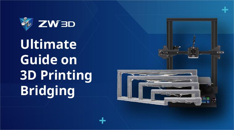
To get a feel for the practical limits, let's watch a video where someone tests this systematically.
How far can a 3d printer "bridge"???
The video "How far can a 3d printer 'bridge'???" from 3D Printer Academy provides a great real-world test of bridging capabilities.
Please watch from the beginning to 01:10, and then from 01:44 to 02:34. This covers the design of the test and the results for bridges of 100mm, 150mm, 200mm, and 250mm. Notice how the quality degrades as the length increases. The key takeaway is that every printer/material combination has a practical limit.
As the video shows, a standard printer can often handle surprisingly long bridges (150-200mm in this case), but there is a clear point of diminishing returns. When you get your printer, performing a similar bridging test will be a valuable calibration exercise.
3. Designing for Bridges in Fusion 360
Understanding the principle is one thing; applying it in your designs is another. Let's look at two powerful techniques for designing features that intelligently use bridging.
Technique 1: Sacrificial Layers
Sometimes you need a clean hole or cavity on the underside of a part, where the top surface would be a large, unsupported overhang. A simple and effective solution is to design a "sacrificial layer"—a thin, one-layer-thick bridge that completely covers the opening.
This layer acts as a built-in support structure. After printing, it's thin enough to be easily cut or punched out, leaving a clean feature behind. This is far more efficient than using slicer-generated supports.
This next video demonstrates this technique beautifully.
Stronger 3D Prints & Less Supports: How to Design for 3D Printing
In the video "Stronger 3D Prints & Less Supports," JanTec Engineering shows how to implement sacrificial layers and other smart bridging techniques.
Please watch the segment from 02:54 to 03:43. This section introduces the concept of sacrificial layers, showing how to model a one-layer-thick extrusion in Fusion 360 to support a hexagonal nut pocket. Notice how this simple trick turns an impossible overhang into a simple bridging operation.
Technique 2: Sequential Bridging (The "Overhanging Counterbore Trick")
For more complex internal features like counterbored holes, there's an even more elegant method that requires no post-processing. Instead of creating one large bridge, you can design a series of small, interlocking bridges that build upon each other layer by layer. This is often called sequential bridging.
The idea is to create a pattern of bridges that gradually close a gap, with each new layer being supported by the bridges from the layer below. The final printed feature is clean, strong, and requires no support removal.
This technique is brilliantly explained in the article "Design for 3D-Printing" on Rahix' Blog. The step-by-step description is excellent for understanding the geometry.
Please read the section titled "The Overhanging Counterbore Trick". Focus on the four-step process described and study the accompanying images. This text explains exactly how to structure the cuts in your model to create the perpendicular bridging layers.
To see this concept in a broader context, the video from JanTec Engineering also touches on it.
Stronger 3D Prints & Less Supports: How to Design for 3D Printing
Let's revisit the video from JanTec Engineering to see a visual example of complex sequential bridging.
Now, watch the section from 03:43 to 04:45. This segment, titled "Bridging Layers," generalizes the counterbore trick and shows an incredible example from the OpenFlexure Microscope project, where a large, complex part is printed entirely without supports using stacked bridges.
By combining these techniques, you can design incredibly complex parts that cleverly manage their own support needs, saving you time, material, and post-processing effort.
4. Your Turn: Design a Bridging Test Piece
In line with your preference for learning by doing, let's design a part in Fusion 360 to test these concepts. Once you have your printer, this will be a perfect first print to calibrate its bridging performance.
Your task: Create a single part that includes the following features:
- Simple Bridge Test: Create a U-shaped frame with three separate horizontal bridges spanning the gap. Make the bridges 20mm, 50mm, and 80mm long. Give them a cross-section of 10mm wide by 3mm tall.
- Sacrificial Layer Test: On a solid block, create a horizontal through-hole for an M5 hex nut (8.0 mm flat-to-flat). Model a 0.2mm thick sacrificial layer that closes off one side of the hole at the bottom of the part.
- Sequential Bridging Test: On the same block, create another M5 hex nut pocket, but this time, implement the "overhanging counterbore trick" using a series of layered cuts as described in the blog post.
This exercise will give you direct practice in modeling these DfAM features.
Conclusion
You've now added another essential DfAM principle to your toolkit. By understanding how and when bridging works, you can move beyond the limitations of simple overhangs and design parts with advanced, self-supporting geometry.
Key Takeaways:
- Bridging is the process of printing a horizontal span between two anchor points, made possible by rapid filament cooling.
- The maximum bridging distance is printer and material dependent. It's crucial to test and understand your own setup's limits.
- Sacrificial Layers are a simple and effective design trick to create support for features on the underside of a part, which are removed after printing.
- Sequential Bridging is an advanced technique where you design a series of small, interlocking bridges to build up complex shapes without any need for supports or post-processing.
In our next lesson, we will shift from managing overhangs and bridges to designing parts that fit together. We'll explore how to apply appropriate clearances for slip-fit and press-fit parts, a critical skill for creating functional assemblies.