Hello! Welcome to the first lesson in our module on Design for Additive Manufacturing (DfAM).
In the previous module, you mastered the slicer workflow, culminating in previewing the toolpath and sending your design to the printer. That workflow assumes the design is final. Now, we're taking a step back to focus on a core principle of DfAM: designing parts specifically for the 3D printing process.
Today's lesson addresses the single most important decision you'll make before any print: how to orient the part on the build plate. This choice has a profound impact on two critical factors: the final strength of your part and the amount of support material required. Mastering this balance is fundamental to creating functional, high-quality prints efficiently.
1. Why Orientation Dictates Strength: The Principle of Anisotropy
If you take a block of wood, you know it's much easier to split it along the grain than against it. Fused Deposition Modeling (FDM) 3D prints behave in a very similar way. The layer-by-layer construction process creates what is known as anisotropy, meaning the part's mechanical properties are not the same in all directions.
A 3D printed part is essentially a stack of fused layers. The bond within a single layer (along the printed lines) is very strong. However, the bond between layers is significantly weaker.
This means a part is strong when forces are applied along its layers, but weak when forces try to pull the layers apart. Given your mechanical engineering background, you'll recognize this as a critical design constraint that has no real equivalent in subtractive manufacturing or injection molding.
To see just how dramatic this effect is, let's watch a video from Stefan at CNC Kitchen, who performs tensile tests on printed samples.
Stop Printing Flat: The 45° Secret for Stronger Parts
This video, "Stop Printing Flat: The 45° Secret for Stronger Parts," provides excellent data-driven evidence for why orientation is so crucial for strength.
Watch from the beginning to 03:04. Pay close attention to the definition of anisotropy and the tensile test results, which show that an upright-printed part can be 50% weaker than one printed flat.
The key takeaway is clear: the adhesion between layers is the weakest link. Therefore, the first rule of orienting for strength is:
Orient your part so that critical forces are applied parallel to the print layers, not perpendicular to them.
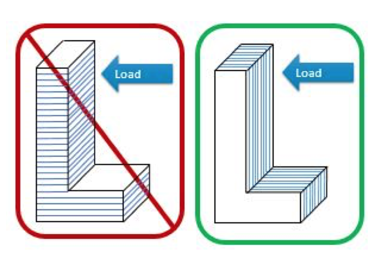
This image provides a perfect visual summary of the principle. For the L-shaped bracket to withstand a load on its vertical arm, it must be printed standing up, so the force is distributed along the strong layer lines.
To delve deeper into this concept, the following guide provides a great textual explanation.
Part Orientation in 3D Printing: Complete Guide
The article "Part Orientation in 3D Printing" offers a detailed look at anisotropic behavior and specific strategies for FDM printing.
Please read the sections titled "Part Strength: The Primary Consideration" (which includes the wood grain analogy) and "FDM Orientation for Maximum Strength." These sections reinforce the core concept and provide actionable strategies.
2. The Second Goal: Minimizing Supports
While strength is often the primary concern for functional parts, your second major goal is to minimize the need for support material. Why?
- Saves Material: Supports are waste material, increasing the cost of your print.
- Saves Time: Printing supports adds significant time to the job.
- Improves Surface Finish: Supports leave behind rough marks on the surfaces they touch, which may require sanding or other post-processing.
- Reduces Labor: Removing supports can be tedious and sometimes risks breaking the part itself.
The most straightforward way to minimize supports is to place the largest, flattest face of your object directly onto the build plate.
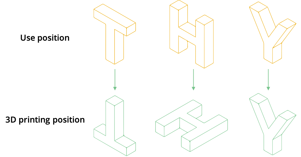
This is a simple but powerful strategy. The guide we looked at earlier also covers this aspect well.
Part Orientation in 3D Printing: Complete Guide
Let's revisit the guide to see how orientation affects material use.
Now, read the section "Material Usage and Cost Optimization," focusing specifically on the subsection "Support Material Minimization."
3. The Trade-Off: When Strength and Simplicity Conflict
You've probably already spotted the problem: The strongest orientation is often not the one that minimizes supports.
Look back at the L-bracket image. The strongest orientation (standing up) creates a large overhang, requiring supports. The easiest orientation to print (lying on its back) is also the weakest. This is the central trade-off of part orientation.
So, what do you do when a part will be stressed in multiple directions, and no single "flat" orientation is strong enough?
The solution is often a compromise: printing at an angle. By orienting a part at, for example, 45 degrees, you can ensure that no single direction is perfectly aligned with the weak layer-adhesion axis. You gain a significant amount of strength compared to the worst-case orientation, at the cost of requiring more complex supports.
Let's return to the CNC Kitchen video to see this principle in action.
Stop Printing Flat: The 45° Secret for Stronger Parts
This next segment demonstrates how printing at an angle provides a practical compromise, backing it up with more test data and a real-world example.
Watch from 06:32 to 09:01, and then from 12:52 to 14:44. The first section shows how angled printing improves strength over the weakest orientation. The second section applies this thinking to a functional vacuum adapter, showing the thought process of choosing a final, angled orientation.
As Stefan demonstrated, angling the part isn't a magic bullet, but it's a powerful strategy for parts that would otherwise have a critical weak point. You can achieve this in Bambu Studio using the Rotate tool or by using the Lay on Face tool to select a non-obvious face or edge to place on the build plate.
Conclusion
You've now learned the fundamental theory behind part orientation. This isn't just a setting to tweak; it's a core design consideration that should be on your mind from the moment you start a new sketch in Fusion 360.
Key Takeaways:
- Anisotropy is Key: FDM prints are weakest between their layers. Always consider how forces will be applied to your final part.
- Strength vs. Supports: The primary goal is to align layers with forces to maximize strength. The secondary goal is to place large, flat faces on the build plate to minimize supports.
- The 45-Degree Compromise: When the above goals conflict, orienting the part at an angle (often 45 degrees) can provide a good balance of strength in multiple directions, at the cost of requiring supports.
- Use Your Tools: In Bambu Studio, experiment with the Rotate and Lay on Face tools. Then, use the Preview tab skills you learned in the last lesson to visualize the support structures and layer lines for each orientation before committing to a print.
In our next lesson, we will put this knowledge into practice in a way that aligns with your preference for hands-on learning. You will design and print a specific test piece to determine the minimum wall thickness and feature size your printer can reliably produce. Understanding orientation will be crucial as you decide how to print that test piece for the most accurate results.