Hello! Welcome back to our module on Design for Additive Manufacturing (DfAM).
In the last lesson, we established the critical importance of part orientation for managing part strength and minimizing supports. We saw that how you place a model on the build plate is a fundamental design decision, not just a slicer setting.
Today, we'll build on that by getting to know the specific capabilities and limitations of your 3D printer. Your goal is to design and print a test piece to determine the minimum wall thickness and feature size that your new Bambu A1 can reliably produce. This aligns perfectly with your preference for learning by designing and testing from scratch, and it's a foundational step for creating any functional part.
1. The 'Why': Understanding Physical and Software Limits
Before you can design a good test, you need to understand what you're testing for. Why can't a printer produce infinitely thin walls or tiny details? The limitations come from both the physical hardware and the slicer software.
- Wall Thickness: In 3D printing, a "wall" is the outer shell of your part, composed of one or more extruded lines called perimeters. The absolute minimum thickness of a wall is determined by the nozzle diameter of your printer (the Bambu A1 comes with a 0.4 mm nozzle). A single wall can't be thinner than the line of plastic extruded from the nozzle.
- Minimum Feature Size: This refers to the smallest detail a printer can accurately create, such as tiny pins, holes, or embossed text. If a feature in your CAD model is too small, the slicer software might ignore it completely because it can't generate a valid toolpath for the nozzle to follow.
To get a solid grasp of these concepts, let's start with a foundational guide.
Design for Additive Manufacturing: Best Practices Guide
The article "Design for Additive Manufacturing: Best Practices Guide" from BigRep clearly defines these core concepts.
Please read the sections titled "Minimal Feature Size" and "Wall Thickness and Layer Height". Focus on how nozzle size and layer height constrain what is physically printable.
Now, let's see how your specific slicer, Bambu Studio, handles these challenges. Modern slicers have clever ways to try and print thin features, but they still have limits.
Introduction to wall generator
The Bambu Lab Wiki provides an excellent explanation of how its slicer generates walls and deals with small features. Understanding this will help you interpret your test print results.
Please read the following sections: "Disadvantages of Classic Walls": This shows why very thin features sometimes disappear after slicing. "Detect Thin Wall": This explains a feature that tries to fix the problem, but can sometimes create other issues. "Minimum wall width" and "Minimum Feature Size": These are the most important sections. They define the specific slicer parameters that control how the thinnest parts of your model are handled. Focus on the relationship between nozzle diameter and the minimum values the slicer can work with.
To give you a general idea of what to expect, designers have created reference guides with typical values. Your own tests will give you the precise numbers for your machine, but this chart provides a good starting point.
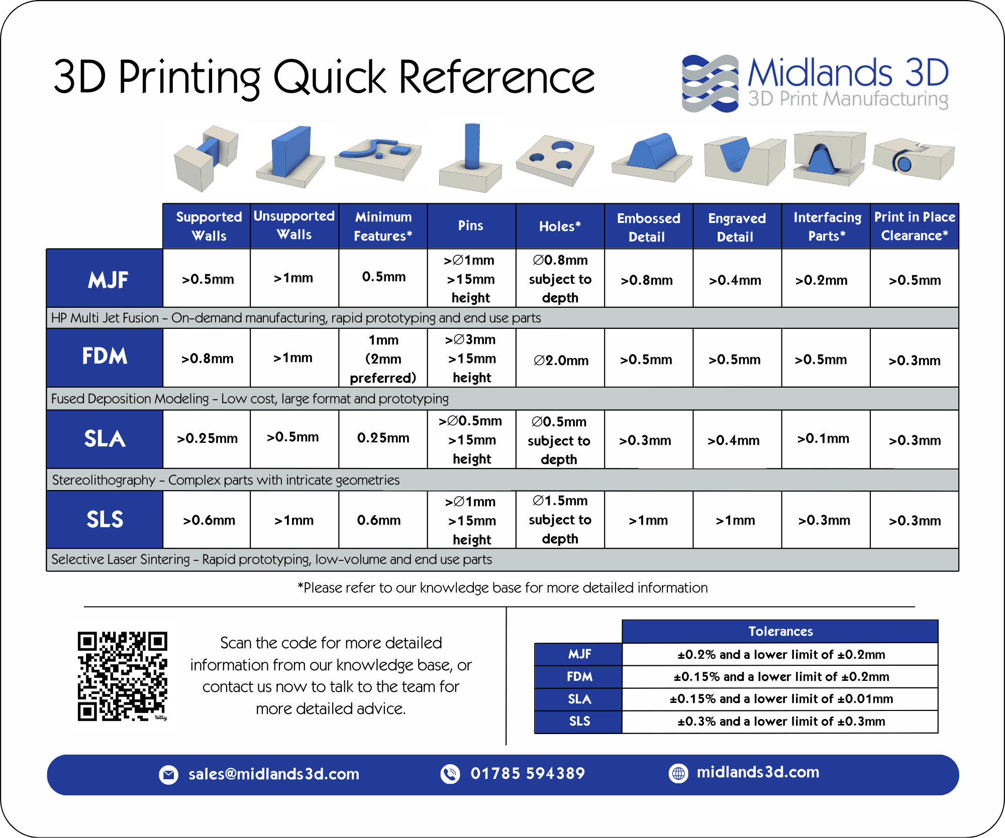
2. The 'How': Designing Your Test Piece in Fusion 360
Now for the hands-on part. You will design a test model in Fusion 360 to empirically find your printer's limits. We will design a part that has a series of walls with progressively decreasing thickness.
A good test piece might look something like this:

Your Design Task:
- In Fusion 360, create a new sketch on the XY plane.
- Design a flat base, for example, 100 mm long, 20 mm wide, and 2-3 mm thick.
- On top of this base, sketch a series of thin rectangles that you will extrude into walls. A good range to test for a 0.4 mm nozzle would be from 1.0 mm down to 0.1 mm.
- Create walls with thicknesses of: 1.0 mm, 0.8 mm, 0.6 mm, 0.5 mm, 0.4 mm, 0.3 mm, 0.2 mm, and 0.1 mm. Make them about 20 mm tall.
- Use the Text tool to label each wall with its thickness on the base. This is also a test of minimum feature size! Make the text extruded (embossed) by about 0.5 mm.
- Extrude the base and the walls.
- Save your design.
This process of sketching, dimensioning, and extruding should be familiar from your earlier work in the course. The goal here is not CAD complexity, but creating a systematic tool for measurement.
3. Printing and Analyzing Your Test
Once your design is complete, export it as a 3MF file and open it in Bambu Studio.
Printing Strategy:
- Orientation: Based on our last lesson, you know that for strength, these walls should be printed standing up, as designed. This orientation also ensures you are testing the wall thickness in the XY plane, which is the most common scenario.
- Slicer Settings for Prototyping: You don't need a beautiful, strong print; you need a fast one. We're just testing for dimensional accuracy. This is a common practice in iterative design.
Designing Your First Functional 3D Printed Parts | Basic Fusion 360 3D Printing
In this video, "Designing Your First Functional 3D Printed Parts," JJ Shankles demonstrates the value of printing quick prototypes to test dimensions. We'll use his advice on slicer settings.
Watch the segment from 13:48 to 14:56. Pay attention to how he adjusts the wall count, infill, and speed to create a "prototype quality" print that finishes quickly. Apply a similar philosophy to your test print: use a low infill (e.g., 10-15%) and just 2 wall loops.
Analysis:
After the print is finished, carefully examine the results:
- Which is the thinnest wall that printed completely?
- Which is the thinnest wall that feels solid and not fragile?
- At what point did the slicer fail to generate a wall at all? (You can also check this beforehand using the "Preview" tab in Bambu Studio).
- How did the embossed text turn out? Is it legible?
The thinnest wall that printed successfully and is reasonably strong is your practical minimum wall thickness. This is a critical number you will use in all future functional designs.
4. A Look Ahead: Testing for Fit and Tolerance
Understanding minimum feature size is the first step. The next is understanding how to design parts that fit together. This involves intentionally leaving a small gap, or clearance, between parts. The ideal clearance depends on your printer's specific dimensional accuracy.
Just like with wall thickness, the best way to determine this is with a dedicated test piece.
Beginner's Guide to Fit and Tolerance in Fusion 360 - Get the Perfect Fit from Your 3D Printer / CNC
The video "Beginner's Guide to Fit and Tolerance" from Practical Alchemy provides a superb introduction to this topic and shows you how to design the next essential test piece for your toolkit.
First, watch from 00:00 to 08:25 to understand the theory of tolerance and the three types of fit: clearance, transition, and interference. Then, watch from 08:25 to 13:17. This section walks through the design and use of a 'fit block' test piece. While you don't need to model this right now, keep it in mind as your next personal project to fully characterize your printer.
Conclusion
In this lesson, you've moved from abstract theory to concrete, empirical measurement. By designing and printing your own test piece, you are discovering the unique "signature" of your manufacturing tool.
Key Takeaways:
- A printer's limits are defined by its hardware (nozzle size) and software (slicer logic).
- The practical minimum wall thickness for a 0.4 mm nozzle is often around 0.4 mm to 0.5 mm, but can vary.
- Features smaller than the slicer's
Minimum Feature Sizemay be ignored or distorted. - Designing and printing standardized test pieces is the most reliable way to characterize your machine's performance for wall thickness, feature size, and clearances.
In the next lesson, we will continue our exploration of DfAM by tackling another fundamental geometric challenge: designing self-supporting features by respecting overhang angles and using chamfers. This will further build your ability to create parts that print efficiently and reliably without extensive support structures.