Hello! Welcome back.
In our last lesson, you learned how to use Section Analysis to slice into your models and inspect how components fit together. This is a crucial skill for verifying clearances and finding interferences, especially for 3D printed parts that need to assemble perfectly.
While Section Analysis is for looking at the interaction between parts, this lesson focuses on the opposite challenge: how to work on a single part without being distracted by the rest of the assembly. As your designs grow in complexity—from a simple tripod to your future custom PC desk—your screen can become cluttered with dozens of components.
This lesson will teach you how to isolate and activate components for focused, efficient editing. Mastering this workflow is key to managing large assemblies and maintaining a clean, organized design history.
1. Activating Components: Setting Your Editing Context
First, let's distinguish between just selecting a component and activating it. When you activate a component, you are telling Fusion 360: "Everything I do from this point forward—every sketch, every extrusion, every fillet—belongs to this specific part."
This has two major effects:
- Visual Focus: All other components in your design become semi-transparent or "ghosted," making it visually clear which part you are working on.
- Parametric Focus: The design timeline at the bottom of the screen filters itself to show only the features belonging to the active component. This is essential for understanding and editing a part's history without the noise of the main assembly's timeline.
Given your mechanical engineering background, you can think of this as taking a specific part out of a larger machine and placing it on your workbench. All the work you do is on that single part before you place it back into the main assembly.
There are two primary ways to activate a component:
- Hover over the component in the Browser and click the radio button (the small circle) that appears to its right.
- Right-click the component in the Browser or in the canvas and select "Activate".
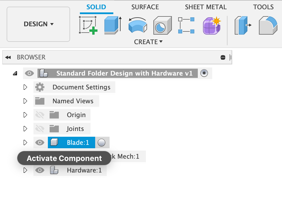
To see this in action and understand its importance, let's watch a brief clip.
Fusion 360 Components and Assemblies Explained | Day 13 of Learn Fusion 360 in 30 Days
The following clip from Product Design Online clearly demonstrates the activation process and the resulting visual change in the assembly.
Watch from 07:19 to 07:45. Pay attention to how the non-active components become grayed out, providing a clear visual focus on the active part.
Activating the correct component before you start modeling ensures that your design remains robust and easy to edit later. All related sketches and features are neatly "contained" within the component they belong to.
2. Isolating Components: Clearing the Clutter
Activating a component is great for focusing your work, but sometimes you need to focus your view. This is where Isolate comes in. Isolating a component is a purely visual tool that temporarily hides every other component in your design.
This is extremely useful when:
- You need to select geometry on the back or inside of a part that is obscured by other components.
- You're working on a very dense assembly and the "ghosted" components are still too distracting.
To isolate a component, simply right-click on it (in the Browser or the canvas) and select Isolate. To bring everything back, right-click again and choose Unisolate.

The common workflow is to first activate the component you want to edit, and then isolate it to get a completely clean workspace.
Master the Timeline, Browser, & Preferences
This blog post from Autodesk provides an excellent summary of both activating and isolating components. It reinforces the concepts we've just discussed.
Read the section titled "Components". Focus on the paragraphs that describe how to activate a component and how the canvas and timeline change. Then, read the final paragraph in that section, which explains the 'Isolate' option.
3. Pro-Tip: Visual Differentiation with Color
In a complex assembly, it can be hard to tell where one component ends and another begins, especially when they share the same default gray appearance. Fusion 360 has a fantastic tool to help with this called Component Color Cycling.
When you toggle this on, Fusion 360 assigns a different color to each component, making them instantly distinguishable in the main canvas. These colors also appear in the Browser and the Timeline, creating a clear visual link between a feature in the timeline and the part it affects.
- Keyboard Shortcut:
Shift + N(Windows) orCtrl + N(Mac). Press it once to turn on, and again to turn off.
Master the Timeline, Browser, & Preferences
The same Autodesk article you just read also explains this feature. Let's take a quick look.
Read the short section titled "Component Color Swatch". This will show you how the color coding works in the timeline and how to toggle it for the physical parts.
This is not just a cosmetic feature; it's a practical tool that helps you understand the structure of your assembly at a glance.
4. Hands-On Practice: Editing the Tripod
Let's apply these techniques to the tripod assembly.
- Open the
Tripodassembly file you've been working on. - In the Browser, find one of the components for the inner, sliding part of a leg (e.g.,
Inner Leg:1). - Activate it by clicking the radio button next to its name. Observe two things:
- The rest of the tripod becomes semi-transparent.
- The timeline at the bottom shortens, showing only the features used to create that leg piece.
- Now, isolate the same component: right-click on it and select
Isolate. The rest of the model should disappear, leaving you with only the inner leg. - With the component isolated and active, let's make a small edit. Use the Chamfer tool (
Modify>Chamfer) to add a small 1mm chamfer to one of the short edges at the end of the leg. - Once the chamfer is applied, unisolate the component by right-clicking it and selecting
Unisolate. The full assembly will reappear. - Finally, reactivate the top-level component (the very first item in the browser) to see the whole model at full opacity. You should see your small chamfer on the leg piece, now in context.
- Press
Shift + Nto toggle Component Color Cycling on and off. See how it makes distinguishing the different parts of the tripod assembly much easier.
This exercise demonstrates the complete workflow: identify, activate, isolate, edit, and then return to the main assembly.
Conclusion
You've now learned the essential workflow for managing and editing individual parts within a larger assembly. This skill is fundamental for maintaining organization and efficiency, especially as you move toward your goal of designing complex multi-part projects like the PC-integrated desk.
Key Takeaways:
- Activate a component to set the editing context. This ensures new features are added to the correct part and isolates its history in the timeline.
- Isolate a component to hide everything else on screen. This is a visual tool for decluttering your workspace.
- The standard professional workflow is to Activate, then Isolate for focused editing.
- Use Component Color Cycling (
Shift+N) to visually differentiate parts in your assembly, timeline, and browser.
This lesson concludes our module on multi-component design. You are now equipped with the core skills to build assemblies: creating components, joining them with motion, inspecting their fit with Section Analysis, and editing them efficiently using Activate and Isolate.
In our next module, we'll make the exciting transition from the digital screen to the physical world. We'll cover everything you need to know to get your 3D printer up and running and prepare your Fusion 360 models for their first print.