Hello! Welcome to the first lesson in our new module, "Advanced ARM Architectures."
In the previous module, we focused on system-level optimizations like low-power modes and clock gating to build power-efficient firmware. We now shift our focus from system-level concerns to the processor core itself. Your work in ADAS and gateway development likely involved complex SoCs that use the powerful cores we're about to study.
This lesson addresses the learning outcome: Describe the key features of the ARMv7-A/R architecture, including the exception model and CP15 system control coprocessor. We will explore the architectures that power high-performance real-time systems (Cortex-R) and application domains capable of running rich operating systems like Linux or QNX (Cortex-A). Understanding these core architectures is fundamental for advanced driver development and debugging in complex automotive systems.
1. The ARMv7 Architecture Profiles: A, R, and M
The ARMv7 architecture isn't a single design but a family of profiles tailored for different applications. You've likely encountered Cortex-M series processors in various ECUs, but for ADAS processing or infotainment, the A-profile and R-profile are far more common.
The ARM University Program, ARM Architecture Fundamentals
To begin, let's watch a section from a lecture by Arm that introduces these three profiles and their intended use cases. This will provide a clear, high-level distinction between the 'Application', 'Real-time', and 'Microcontroller' profiles.
Please watch from 11:36 to 17:25. Pay close attention to the key features mentioned for each profile, such as Memory Management Units (MMUs) for the A-profile and deterministic behavior for the R-profile.
As the video explained, here’s a summary of the key distinctions relevant to your work:
-
ARMv7-A (Application):
- Target: High-performance systems running rich operating systems (e.g., Linux, QNX, Android). Think of the main processor in an infotainment system or a central ADAS compute unit.
- Key Feature: Includes a full Memory Management Unit (MMU), which enables virtual memory. This is essential for protecting memory between different applications and the OS kernel.
- Additional Features: Supports extensions like ARM TrustZone for security and hardware virtualization.
-
ARMv7-R (Real-time):
- Target: High-performance, safety-critical systems requiring deterministic, real-time responses. Examples include RADAR sensor processing, engine management, or braking systems.
- Key Feature: Includes a Memory Protection Unit (MPU) instead of an MMU. An MPU provides memory protection but does not support virtual memory, which helps ensure predictable timing. It also features tightly-coupled memories (TCMs) for fast, deterministic access to code and data.
- Additional Features: Optimized for low interrupt latency.
-
ARMv7-M (Microcontroller):
- Target: Cost-sensitive, general-purpose microcontroller applications.
- Key Feature: Features a much simpler programmer's model and exception system (the Nested Vectored Interrupt Controller, or NVIC, which we will contrast later). It is designed for low gate count and low power consumption.
For the rest of this lesson, we will focus on the features common to the ARMv7-A and ARMv7-R profiles.
2. The ARMv7-A/R Programmer's Model: Processor Modes
A fundamental difference between the A/R profiles and the M profile is the concept of processor modes. While a Cortex-M processor has two simple modes (Thread and Handler), an ARMv7-A/R processor has multiple modes, each with a specific purpose and privilege level. This is central to how they handle exceptions and protect system resources.
The official ARM documentation provides the most precise definition of these modes. This page contains a table that clearly lists each mode, its purpose, and its privilege level.
Read the introductory text and study the table in 'Table 10.1. ARM processor modes'. Then, read the 'Notes on the ARM processor modes' section to understand the distinction between User, Privileged, and Exception modes.
The modes you just read about can be summarized as:
| Mode | Privilege | Purpose |
|---|---|---|
User (usr) |
Unprivileged | For running normal application code. Access to system resources is restricted. |
System (sys) |
Privileged | For running OS tasks that need privileged access but not a separate register set. |
Supervisor (svc) |
Privileged | Entered on reset or when an SVC (supervisor call) instruction is executed. Used by the OS kernel. |
Abort (abt) |
Privileged | Entered on a memory access error (e.g., data or prefetch abort). |
Undefined (und) |
Privileged | Entered when the processor tries to execute an unknown instruction. |
IRQ (irq) |
Privileged | Entered when a standard Interrupt Request occurs. |
FIQ (fiq) |
Privileged | Entered on a Fast Interrupt Request, designed for lower latency than IRQ. |
This multi-mode system allows an operating system to run in a privileged mode (svc) where it has full control, while running user applications in the restricted usr mode. This prevents buggy or malicious applications from corrupting the OS or other applications.
3. Banked Registers and the Exception Model
When the processor switches from User mode to an exception mode (like IRQ or Abort), it must not corrupt the registers of the code that was interrupted. ARMv7-A/R processors solve this with banked registers. This means that some physical registers are swapped out for different ones depending on the current processor mode.
Windows on ARM - An assembly language primer
This article provides a very practical breakdown of the ARM registers and clearly illustrates the concept of banking. The tables are especially helpful for visualizing which registers are available in each mode.
Read the 'Registers' section. Focus on the two tables: the first describes the purpose of each register (r0-r15), and the second is crucial for understanding banking, showing how registers like SP, LR, and SPSR are unique to each exception mode.
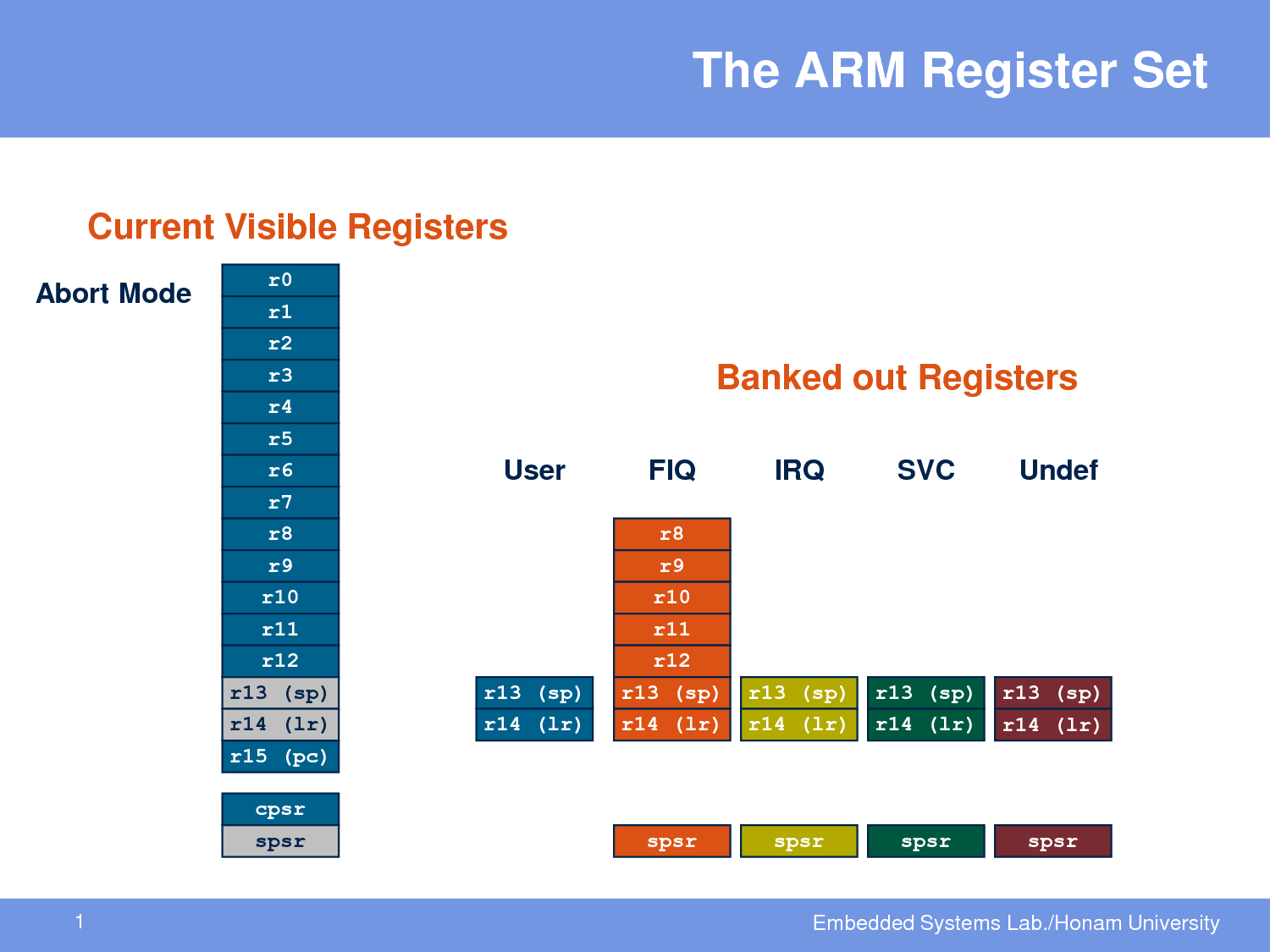
The key banked registers for exception handling are:
r13(Stack Pointer, SP): Each exception mode has its own stack pointer, so each can have its own private stack. This prevents the interrupt handler's stack from overflowing into the application's stack.r14(Link Register, LR): When an exception occurs, the return address is stored in theLRof that exception's mode. This is how the processor knows where to resume execution after the handler finishes.- Saved Program Status Register (
SPSR): This is perhaps the most important. Each exception mode has its ownSPSR. When an exception is taken, the processor automatically copies the Current Program Status Register (CPSR) into theSPSRof the new mode. TheCPSRcontains the ALU flags, interrupt mask bits, and—most importantly—the processor mode just before the exception. To return from the exception, the handler just has to restore theCPSRfrom theSPSR, which atomically returns the processor to its previous state and mode.
The Exception Sequence
This all comes together in a precise sequence when an exception occurs:
The ARM University Program, ARM Architecture Fundamentals
This animated segment from the Arm lecture clearly visualizes the step-by-step process of taking an exception. It shows how the registers and program flow are managed by the hardware.
Watch the section from 30:39 to 32:44. Observe how the CPSR is saved to the SPSR, the PC is saved to the LR, and how the processor uses the vector table to find the handler.
To summarize the process:
- The processor finishes the current instruction.
- It copies the
CPSRto theSPSRof the target exception mode. - It saves the return address in the
LRof the target exception mode. - It changes the processor mode bits in the
CPSRto the exception mode. - It forces the Program Counter (
PC) to jump to the corresponding entry in the Exception Vector Table.
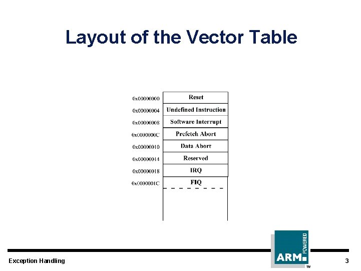
This vector table is located at an address specified by a special register, which brings us to our final topic.
4. The CP15 System Control Coprocessor
How do you control core features like the location of the vector table, caches, or the MMU? In ARMv7-A/R, this is done via the System Control Coprocessor, also known as CP15.
A coprocessor is a hardware unit that works alongside the main processor. CP15 is not for general-purpose computing; it's a dedicated interface for configuring and controlling the core itself. You can't access it with standard MOV or LDR instructions. Instead, you use special assembly instructions:
MRC: Move from Coprocessor to ARM Register. (Read from CP15).MCR: Move to Coprocessor from ARM Register. (Write to CP15).
Windows on ARM - An assembly language primer
The same article we read earlier has a fantastic, practical introduction to the CP15 coprocessor and its registers. It shows how a real-world OS uses these registers to manage the system.
Read the sections 'Co-Processor' and 'Exception Handling'. Focus on what CP15 is used for, the MRC/MCR instruction format, and the roles of key registers like SCTLR, VBAR, and the fault status/address registers.
The CP15 registers are a critical part of the architecture. Here are a few key ones you should know:
c1, SCTLR(System Control Register): The main control register. It has bits to enable/disable the MMU, data/instruction caches, alignment checking, and more.c12, VBAR(Vector Base Address Register): This register holds the base address of the exception vector table. An OS will set this during boot to point to its own table.c5, DFSR/IFSR(Data/Instruction Fault Status Registers): When anAbortexception occurs, these registers contain information about why the memory access failed (e.g., permission fault, translation fault).c6, DFAR/IFAR(Data/Instruction Fault Address Registers): These registers capture the memory address that caused theAbortexception.
Your experience with the Trace32 debugger is very relevant here. When debugging a hard fault on an ARMv7-A/R core, one of the first things you would do is connect the debugger, check the processor mode (it would likely be Abort), and then use the debugger to read the CP15 fault registers (DFAR, DFSR) to begin your diagnosis.
Test your understanding!
You are debugging a system running on an ARMv7-A processor. The system crashes, and the debugger shows the processor is now in Abort mode. The lr_abt register holds the address 0x40001238, and the DFAR (Data Fault Address Register) in CP15 holds the address 0x00000010. What do these two pieces of information tell you?
Show answer
- The
DFARvalue of0x00000010indicates that the processor tried to perform a data access (read or write) to the memory address0x10. This is a very low address and is often part of a null-pointer dereference (e.g., trying to access a member of a struct through a null pointer, likeptr->memberwhereptrisNULLandmemberis at an offset). - The
lr_abtvalue of0x40001238tells you the address of the instruction that should be executed after the faulting instruction. By examining the code at or just before this address (e.g., at0x40001234), you will find theLDRorSTRinstruction that attempted the invalid memory access.
5. Interview Corner
Your deep experience in automotive software is valuable, and an interviewer will want to see if you can connect it to low-level architectural knowledge.
Q1: "Could you contrast the exception models of ARM Cortex-M and Cortex-A/R processors?"
A: You can explain that Cortex-M uses the NVIC, which is a standardized interrupt controller with a simple vector table of addresses and automatic hardware stacking of key registers. In contrast, Cortex-A/R uses a more flexible system based on processor modes. When an exception occurs, it switches to a specific mode (like IRQ, Abort), uses banked registers (SP, LR, SPSR) to preserve context, and jumps to an instruction in a vector table. This model is more complex but gives an OS finer control over system state and resources.
Q2: "You are writing a driver for a peripheral on a system with an ARMv7-A core running a full OS. How would your application code typically trigger a function in your driver, and what architectural mechanisms are involved?"
A: You could explain that the application, running in unprivileged User mode, can't access hardware directly. It would make a system call, which is a controlled entry into the OS kernel. This is often done with the SVC (Supervisor Call) instruction. Executing SVC causes an exception, switching the processor to the privileged Supervisor mode. The OS's SVC handler then validates the request and calls the appropriate kernel-space driver function, which can now run with the necessary privileges to access the peripheral's memory-mapped registers.
Conclusion
In this lesson, we've taken a significant step into the world of high-performance ARM cores. You now have a solid understanding of the fundamental differences between the A, R, and M profiles and the core architectural features that define ARMv7-A/R.
Key Takeaways:
- ARMv7 is a family of profiles: A for Applications (with MMU), R for Real-time (with MPU), and M for Microcontrollers.
- The ARMv7-A/R exception model is built on processor modes (User, Supervisor, IRQ, etc.), which define privilege levels.
- Banked registers, especially
SP,LR, and theSPSR, are used to quickly save and restore context when switching modes during an exception. - The CP15 System Control Coprocessor is a privileged interface, accessed via
MRCandMCRinstructions, used to configure core functionality like caches, memory protection, and the exception vector base address (VBAR).
Next Lesson Preview:
We've mentioned the Memory Management Unit (MMU) as a key feature of the A-profile. In our next lesson, we will dive deep into its purpose and operation. You will learn about virtual-to-physical address translation, page tables, and how an MMU enables the memory protection and virtualization required by modern operating systems. This knowledge is essential for understanding how complex software runs on high-end automotive processors.