Hello! Welcome to your next lesson on advanced ARM architectures.
In our previous session, we explored the theory behind the Memory Management Unit (MMU). We covered its core purpose—providing memory protection and abstraction—and dissected the process of virtual-to-physical address translation through page tables, Page Table Entries (PTEs), and the all-important Translation Lookaside Buffer (TLB).
Today, we transition from theory to practice. This lesson directly addresses the learning outcome: Write code to configure the MMU by setting up a basic page table and enabling translation. We will walk through the specific sequence of operations, from allocating memory for a page table to flipping the switch that brings the MMU to life. As a first, safe step, we'll implement an identity mapping, where every virtual address maps to the exact same physical address.
The Four Steps to Enable the MMU
Enabling the MMU on an ARMv7-A/R processor is a precise sequence. Any misstep can lead to an immediate system crash (an Abort exception), so understanding the order is critical. The process can be broken down into four main steps:
- Create the Translation Tables: You must first define the address mappings in memory. These tables are the "map" the MMU will use.
- Configure the Translation Table Base Register (TTBR): You need to tell the MMU hardware where to find the translation tables you just created.
- Set Domain Access Controls: You need to configure the access policies for different memory regions.
- Enable the MMU in the System Control Register (SCTLR): This is the final step where you activate the MMU.
Let's work through each of these steps.
Step 1: Creating the Translation Table
As we discussed, page tables can be multi-level to save memory. However, the simplest configuration uses only a single, first-level (L1) translation table. In this scheme, the entire 4GB virtual address space is divided into 4096 x 1MB blocks called sections.
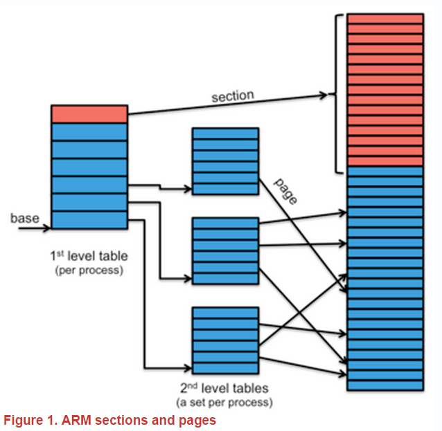
Our goal is to create a table in RAM that contains 4096 entries, where each entry, known as a section descriptor, defines the mapping for a 1MB region.
Turning on an ARM MMU: Understanding the Code Behind It
To understand the structure of this table and its entries, let's turn to the article 'Turning on an ARM MMU: Understanding the Code Behind It'. This first reading covers the concept of multi-level tables and the different page sizes available.
Read the section that begins with 'The ARM MMU supports entries in the translation tables...' and ends just before 'Now let’s get on with some coding!'. Focus on the different mapping sizes (1MB section, 64KB/4KB pages) and why we might choose one over the other.
The Section Descriptor Format
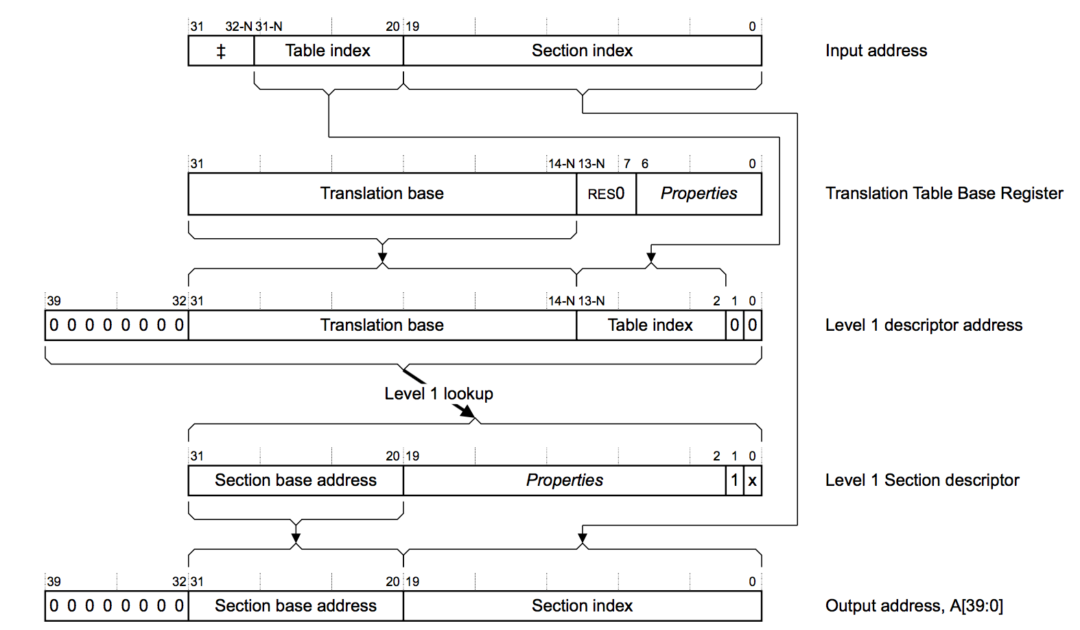
Each 32-bit entry in the L1 table must be formatted correctly. For a section descriptor, the format is as follows:
Turning on an ARM MMU: Understanding the Code Behind It
The same article details the bit fields within a section descriptor. Understanding this format is key to writing the code that builds the page table.
Read the part starting 'The next step is to populate the tables...' down to '...increment by 1MB (or 0x1) each time.'. Pay close attention to the bit fields described: Section Base Address, Access Permissions, Domain, and the Cacheable/Bufferable bits.
Here is a summary of the key bits in a section descriptor:
- Bits [31:20]: Section Base Address. This is the top 12 bits of the 1MB-aligned physical address.
- Bits [11:10]: Access Permissions (AP). Controls read/write access from Privileged and Unprivileged modes.
- Bits [8:5]: Domain. A number from 0-15 that groups memory regions for coarse-grained access control.
- Bit [3]: C (Cacheable) bit.
- Bit [2]: B (Bufferable) bit.
- Bits [1:0]: Must be
0b10to signify a section descriptor.
Writing Code to Create an Identity Map
Now, let's write C code to create an identity-mapped L1 table. For an identity map, the physical base address in each descriptor must match the virtual address it represents.
The L1 table must be 16KB aligned. We can use a GCC attribute to ensure this.
#include <stdint.h>

#define L1_TABLE_ENTRIES 4096
#define L1_TABLE_ALIGNMENT 16384 // 16KB

// Define the L1 page table, ensuring it is 16KB aligned.
uint32_t l1_page_table[L1_TABLE_ENTRIES] __attribute__((aligned(L1_TABLE_ALIGNMENT)));

// Function to populate the L1 page table with an identity mapping.
void create_identity_map(void) {
    uint32_t section_base_addr = 0;

    for (int i = 0; i < L1_TABLE_ENTRIES; i++) {
        // For each 1MB section, create a descriptor.
        uint32_t descriptor = 0;

        // Bits [31:20]: Section Base Address
        descriptor |= (section_base_addr & 0xFFF00000);

        // Bits [11:10]: AP[2:1] = 11. Full access for Privileged and User modes.
        descriptor |= (3 << 10);

        // Bits [8:5]: Domain = 0. We'll configure Domain 0 later.
        descriptor |= (0 << 5);

        // Bit [4]: Must be 1 for ARMv5 and later.
        descriptor |= (1 << 4);

        // Bit [3]: C bit (Cacheable). Set to 1.
        // Bit [2]: B bit (Bufferable). Set to 1.
        // Memory type is Outer and Inner Write-Back, Write-Allocate Cacheable.
        descriptor |= (1 << 3) | (1 << 2);

        // Bits [1:0]: 0b10 for a section descriptor.
        descriptor |= (2 << 0);

        l1_page_table[i] = descriptor;

        // Move to the next 1MB section.
        section_base_addr += 0x100000;
    }
}
This loop creates 4096 section descriptors, mapping the entire 4GB virtual space (0x00000000 to 0xFFFFFFFF) to the exact same physical addresses.
Steps 2-4: Configuring and Enabling the MMU with Assembly
With the table created in memory, the remaining steps involve writing to special system control registers. These are accessed via the coprocessor p15 using the mrc (Move from Coprocessor) and mcr (Move to Coprocessor) instructions. Since direct register access is required, this is typically done in assembly or C inline assembly.
Turning on an ARM MMU: Understanding the Code Behind It
The same article provides the necessary assembly code snippets to configure the system registers and finally enable the MMU. Let's study them.
First, review the assembly code snippet in the section 'Now let’s get on with some coding!'. Focus on the 'mcr' instruction that writes to register c2 of p15 to set the translation table base. Then, jump to the section 'There is one more concept we need to understand – Domains...'. Read about setting the domain access control (register c3) and, most importantly, the three lines of code that read, modify, and write back to control register c1 to enable the MMU by setting bit 0.
Here are C functions using inline assembly that perform these steps:
Step 2: Configure the TTBR
The Translation Table Base Register 0 (TTBR0) holds the physical address of our L1 table.
void set_ttbr0(uint32_t table_base_addr) {
    // Invalidate the entire TLB. This is crucial before changing address spaces.
    __asm__ volatile("mcr p15, 0, %0, c8, c7, 0" : : "r"(0));

    // Write the physical base address of our L1 table to TTBR0.
    // The register is p15, c2, c0, 0.
    __asm__ volatile("mcr p15, 0, %0, c2, c0, 0" : : "r"(table_base_addr));
}
Step 3: Set Domain Access Control
We assigned all our descriptors to Domain 0. Now we must configure the Domain Access Control Register (DACR) to define the permissions for this domain. We'll set it to "Manager" mode, which means the access permissions in the PTEs themselves are used, without an extra layer of checks.
void set_dacr(void) {
    uint32_t dacr_value = 0;

    // Set Domain 0 to 'Manager' (0b11).
    // All other domains (1-15) are set to 'No Access' (0b00).
    dacr_value |= (3 << 0);

    // Write the value to DACR.
    // The register is p15, c3, c0, 0.
    __asm__ volatile("mcr p15, 0, %0, c3, c0, 0" : : "r"(dacr_value));
}
Step 4: Enable the MMU
This is the final, irreversible step. We set the M-bit (bit 0) in the System Control Register (SCTLR). This is always done with a read-modify-write sequence to preserve other important settings in the register.
void enable_mmu(void) {
    uint32_t sctlr_value;

    // Read the SCTLR. The register is p15, c1, c0, 0.
    __asm__ volatile("mrc p15, 0, %0, c1, c0, 0" : "=r"(sctlr_value));

    // Set the M-bit (bit 0) to enable the MMU.
    sctlr_value |= (1 << 0);

    // Write the modified value back to the SCTLR.
    __asm__ volatile("mcr p15, 0, %0, c1, c0, 0" : : "r"(sctlr_value));
}
Crucial Point: The moment the mcr instruction to SCTLR completes, the MMU is active. All subsequent instruction fetches and data accesses are subject to address translation. If the page table is not correctly configured for the memory where your code is currently running, the processor will immediately take a Prefetch Abort exception and crash. This is why an identity map is such a safe and common first configuration.
Test your understanding!
You are tasked with setting up an MMU. You've written the C code to generate the L1 page table for an identity map, and you've written the assembly to set the TTBR0 and DACR. You then write a single value of 0x1 directly to the SCTLR to enable the MMU, instead of performing a read-modify-write. What is a likely negative consequence of this action?
Show answer
The SCTLR controls many features besides the MMU, such as cache enabling, alignment checking, and exception vector locations. By writing 0x1 directly, you are not only setting the MMU enable bit, but you are also clearing all other bits to 0. This could, for example, disable the instruction and data caches (leading to a massive performance drop) or change the exception vector base address, which could cause the system to crash on the next exception. The correct procedure is always to read the current SCTLR value, modify only the bit(s) you intend to change, and write the result back.
Interview Corner
This topic is a prime target for in-depth technical interviews for low-level roles.
Q1: "Walk me through the high-level steps and the key registers you would configure on an ARMv7 processor to enable the MMU with a simple 1:1 memory mapping."
A: "First, I'd create a 16KB-aligned first-level (L1) page table in memory. I would program a loop to fill its 4096 entries, where each entry is a 1MB section descriptor. For an identity map, the Section Base Address in each descriptor would match the virtual address it represents. Next, I would invalidate the TLB and then write the physical base address of this page table into the TTBR0 register using an mcr instruction. After that, I would configure the DACR to set the relevant domain (e.g., Domain 0) to 'Manager' mode. Finally, I would perform a read-modify-write on the SCTLR, setting bit 0 to enable the MMU."
Q2: "What is an identity map, and why is it a useful first step when bringing up a system?"
A: "An identity map is a memory mapping where every virtual address is translated to the identical physical address (e.g., virtual 0x80001000 maps to physical 0x80001000). It's useful during system boot-up because it allows you to enable the MMU without changing the address space. This is a safe way to turn on memory protection and caching features early in the boot process before a more complex virtual memory layout for an OS kernel and user applications is established."
Q3: "After you write to the SCTLR to enable the MMU, the system immediately crashes with a data abort. What are the first things you would check in your MMU setup code?"
A: "My first check would be the page table entry corresponding to the memory region where my data and stack are located. The abort likely means either the mapping is wrong (the physical address is incorrect), or the access permission bits in the descriptor do not allow the operation (e.g., trying to write to a read-only page). I would also verify that the base address in TTBR0 is correct and that the L1 table itself is properly aligned in memory. Using a debugger like Trace32, I would halt before enabling the MMU, inspect the page table in memory, and single-step through the SCTLR write to see exactly where it fails."
Conclusion
Today you've bridged the gap from MMU theory to concrete implementation. You now have the sequence and the code required to initialize and enable the MMU on an ARMv7-A/R processor.
Key Takeaways:
- MMU initialization follows a strict sequence: create tables, set TTBR, set DACR, enable SCTLR.
- The simplest mapping is a first-level table using 1MB sections. An identity map is a safe starting point.
- Configuration requires writing to system control registers (
TTBR0,DACR,SCTLR) usingmcr/mrcinstructions, often via inline assembly in C. - A read-modify-write strategy is essential when changing the
SCTLR. - The moment the MMU is enabled, all memory accesses are translated. Any error in the setup will likely cause an immediate crash.
Next Lesson Preview:
In the next lesson, we will cover another critical aspect of memory management: implementing data cache maintenance operations. Now that we can enable the MMU and caches, we must learn how to ensure that the CPU's view of memory (the cache) and the actual physical memory are consistent, which is a frequent source of complex bugs in systems with DMA or multiple bus masters.