Hello! Welcome back to our course on AUTOSAR MCAL Development.
In our last lesson, we saw how to implement the Port and Dio drivers, establishing the core AUTOSAR principle of using a generated configuration structure to program the hardware. We learned how the Port driver handles one-time pin configuration, while the Dio driver manages runtime I/O.
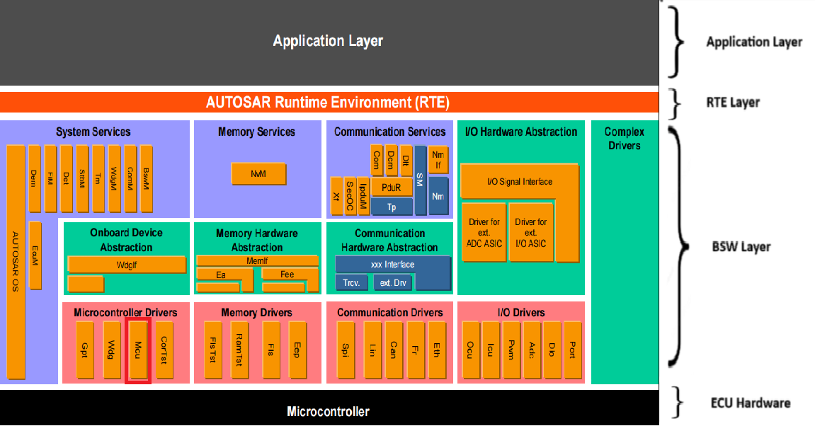
However, before any pin can be configured or any digital signal can be read, the microcontroller unit (MCU) itself must be in a stable, operational state. This is the fundamental responsibility of the MCU driver. Today, we will implement the core of this driver. Our learning outcome is to implement the AUTOSAR Mcu driver state machine, including clock and RAM initialization. You'll see that a correct Mcu initialization is the bedrock upon which all other MCAL drivers stand.
1. The Mcu Driver: The Heart of the MCAL
The Mcu driver is the first piece of MCAL software to run after the low-level startup code. It is responsible for foundational MCU services that enable all other functionalities.
Let's start with the official AUTOSAR specification to understand the scope of the Mcu driver. This document outlines its primary features.
Please read the 'Introduction and functional overview' section. Focus on the list of features provided, specifically noting the initialization of clock, PLL, and RAM sections.
As the specification highlights, the Mcu driver's main jobs during initialization are:
- Clock Initialization: Configuring oscillators, PLLs, and clock prescalers to provide the correct operating frequencies for the CPU and peripherals.
- RAM Initialization: Initializing specified RAM sections to a known default value.
- Power Mode Management: Providing services to enter low-power modes (which we will explore in a later lesson).
2. The Mcu Initialization State Machine
Unlike a simple Port_Init call, the Mcu initialization follows a specific sequence, especially when a Phase-Locked Loop (PLL) is used to generate the main system clock. This sequence ensures that the system only switches to a new clock source after it has become stable.
The best way to understand this flow is by looking at the example sequence diagram from the AUTOSAR specification.
The following sequence diagram from the AUTOSAR SWS for the Mcu Driver illustrates the standard initialization flow. It's a critical concept to grasp.
Please study Figure 9.1, 'Sequence Diagram - Mcu Initialization'. Pay close attention to the order of calls: Mcu_Init, Mcu_InitClock, Mcu_GetPllStatus, and Mcu_DistributePllClock.
This sequence defines an implicit state machine:
- UNINIT State: The initial state before any Mcu functions are called.
Mcu_Init(): The application calls this first. The driver transitions to the INITIALIZED state. This function reads the configuration pointer and prepares the driver for other API calls.Mcu_InitClock(): The application calls this to configure the clock hardware based on a selected configuration set. Critically, if a PLL is being configured, this function starts the PLL locking procedure but does not wait for it to complete. The PLL is now in a PENDING state.Mcu_GetPllStatus(): The application must now poll the PLL status. It repeatedly calls this function until it returnsMCU_PLL_LOCKED.Mcu_DistributePllClock(): Once the PLL is locked, the application calls this function. The driver switches the main system clock from the initial source (e.g., an internal oscillator) to the new, stable PLL output. The clock system is now in its final, high-speed state.Mcu_InitRamSection(): This can be called any time afterMcu_Init(). It iterates through a configured RAM section and fills it with a default value.
This asynchronous handling of the PLL is crucial. PLLs take a non-trivial amount of time to stabilize. Instead of blocking the entire startup process, AUTOSAR defines this non-blocking pattern, allowing other initializations (that don't depend on the final clock speed) to potentially run in parallel.
3. Implementing Clock Initialization
The real complexity of the Mcu driver lies in the clock configuration. A modern automotive MCU has a complex clock tree with multiple sources (internal/external oscillators) and paths.
Just like with the Port driver, this complexity is managed through configuration. In your configuration tool (e.g., EB Tresos), you define one or more McuClockSettingConfig containers. Each container represents a complete clock tree setup: PLL multipliers, bus prescalers, peripheral clock enables, etc.
MCU 3.0 driver user guide, TRAVEO™ T2G family
To get a practical feel for what goes into a clock configuration, let's look at a vendor-specific user guide. This document details the vast number of parameters for a real-world MCU.
Skim through section 4.5, 'MCU clock setting configuration', particularly subsections 4.5.2 ('MCU clock settings') and 4.5.2.3 ('MCU PLL clock settings'). You don't need to memorize the parameters; the goal is to appreciate the level of detail involved in specifying PLL sources, dividers, and output frequencies.
The Mcu_InitClock Implementation
The Mcu_InitClock function takes an ID that corresponds to one of the McuClockSettingConfig containers you've defined. The implementation then uses this ID to find the correct settings in the generated Mcu_ConfigType structure and programs the hardware.
Here is a conceptual implementation. The register names are for illustration but the logic is universal.
// In Mcu_Cfg.c (generated file)
const Mcu_ClockConfigType McuClockSettings[] = {
    [0] = { // Corresponds to McuClockSettingId 0
        .pllSource = MCU_PLL_SRC_HSE,
        .pllMul = 336,
        .pllPDiv = 4,
        .ahbPrescaler = 1,
        .apb1Prescaler = 4,
        .apb2Prescaler = 2
    },
    // ... other clock settings
};

// In Mcu.c (driver implementation)
Std_ReturnType Mcu_InitClock(Mcu_ClockType ClockSetting) {
    // 1. Validate ClockSetting ID and driver state (must be initialized)
    if (Mcu_DriverState != MCU_INITIALIZED) { /* report MCU_E_UNINIT */ return E_NOT_OK; }
    if (ClockSetting >= MAX_CLOCK_SETTINGS) { /* report MCU_E_PARAM_CLOCK */ return E_NOT_OK; }

    // 2. Get the specific clock configuration from the generated structure
    const Mcu_ClockConfigType* clkConf = &Mcu_ConfigPtr->ClockConfigs[ClockSetting];

    // 3. Configure the PLL. First, ensure PLL is off.
    // (Example for STM32 RCC peripheral)
    RCC->CR &= ~RCC_CR_PLLON;
    // Wait for PLL to be disabled
    while((RCC->CR & RCC_CR_PLLRDY) != 0);

    // 4. Write the configuration values from the struct to the PLL config register
    RCC->PLLCFGR = (clkConf->pllSource << 22) |
                   (clkConf->pllMul << 6) |
                   (clkConf->pllPDiv << 16);

    // 5. Enable the PLL and return. We DO NOT wait for the lock flag here.
    RCC->CR |= RCC_CR_PLLON;

    // 6. Set prescalers for AHB/APB buses
    RCC->CFGR |= (clkConf->ahbPrescaler << 4) |
                 (clkConf->apb1Prescaler << 10) |
                 (clkConf->apb2Prescaler << 13);

    // Remember the PLL is now attempting to lock.
    Mcu_PllState = MCU_PLL_PENDING;

    return E_OK;
}
4. Implementing RAM Initialization
Initializing RAM sections is a more straightforward task. The configuration defines one or more RAM sectors, each with a base address, a size, and a default value to write.
Let's review the standard configuration parameters for a RAM section.
Find section 10.2.7, 'McuRamSectorSettingConf'. Note the four key parameters: McuRamSectionBaseAddress, McuRamSectionSize, McuRamDefaultValue, and McuRamSectionWriteSize.
The Mcu_InitRamSection function takes the ID of a configured RAM section and performs what is essentially a memset operation.
The Mcu_InitRamSection Implementation
// In Mcu.c (driver implementation)
Std_ReturnType Mcu_InitRamSection(Mcu_RamSectionType RamSection) {
    // 1. Validate RamSection ID and driver state
    if (Mcu_DriverState != MCU_INITIALIZED) { /* report MCU_E_UNINIT */ return E_NOT_OK; }
    if (RamSection >= MAX_RAM_SECTIONS) { /* report MCU_E_PARAM_RAMSECTION */ return E_NOT_OK; }

    // 2. Get the specific RAM configuration from the generated structure
    const Mcu_RamConfigType* ramConf = &Mcu_ConfigPtr->RamConfigs[RamSection];

    // 3. Cast the base address to a volatile pointer. 'volatile' is critical to prevent
    //    the compiler from optimizing away these memory writes.
    volatile uint8_t* pRam = (volatile uint8_t*)ramConf->BaseAddress;
    uint32_t size = ramConf->Size;
    uint8_t defaultValue = ramConf->DefaultValue;

    // 4. Loop through the section and write the default value
    for (uint32_t i = 0; i < size; i++) {
        pRam[i] = defaultValue;
    }

    return E_OK;
}
Test your understanding!
An application requires a very fast startup time. The system clock needs to be switched to a 168 MHz PLL, but there's a CAN driver initialization that doesn't depend on this high speed and could run earlier. How would you structure the initialization calls to optimize startup time, and which Mcu function acts as the "gate" before the rest of the application can run at full speed?
Show answer
You would structure the calls to leverage the asynchronous nature of the PLL locking:
Mcu_Init()Mcu_InitClock()// This starts the 168 MHz PLL locking but returns immediately.Can_Init()// The CAN driver initialization can run now, using the default, slower internal clock.while (Mcu_GetPllStatus() != MCU_PLL_LOCKED) { /* wait */ }// Poll for PLL stability.Mcu_DistributePllClock()// This is the "gate". After this call, the system is running at 168 MHz.- Now, run the rest of the initializations that depend on the high-speed clock.
5. Interview Corner
Q1: Describe the typical initialization sequence for the AUTOSAR Mcu driver when using a PLL. Why is this sequence important?
A: The sequence is Mcu_Init(), Mcu_InitClock(), a polling loop with Mcu_GetPllStatus(), and finally Mcu_DistributePllClock(). This sequence is critical because PLLs require time to stabilize and achieve a frequency lock. Mcu_InitClock only starts the process. The polling loop ensures we wait until the clock is stable, and Mcu_DistributePllClock performs the final, safe switchover to the PLL as the system clock source. Attempting to switch before the PLL is locked would lead to an unstable system clock and likely a crash.
Q2: What is the difference between Mcu_InitClock and Mcu_DistributePllClock?
A: Mcu_InitClock is the configuration function. It writes settings from the configuration structure to the clock control registers, programming the PLL's dividers and multipliers, and then enables the PLL. It starts the locking process. Mcu_DistributePllClock is the activation function. It changes the system's clock multiplexer to select the (now stable) PLL output as the main clock source. It's the final step that makes the high-speed clock active for the CPU and peripherals.
Q3: You're bringing up a new board, and the application hangs during BSW initialization. You suspect a clock issue. Using a Lauterbach JTAG debugger, what registers would you inspect within the Mcu driver's logic?
A: I would trace the Mcu initialization sequence and inspect the relevant clock control registers at each step.
- After
Mcu_InitClock: I'd check the PLL configuration register (e.g.,RCC_PLLCFGR) to ensure the multiplier and divider values match my configuration. I'd also check the clock control register (e.g.,RCC_CR) to confirm thePLLONbit is set, indicating the PLL has been enabled. - During the
Mcu_GetPllStatusloop: I would monitor the clock control register'sPLLRDY(PLL Ready) bit. If this bit never gets set, it indicates a hardware problem or a misconfiguration of the PLL input clock or frequency range. - After
Mcu_DistributePllClock: I would inspect the main clock configuration register (e.g.,RCC_CFGR) to check theSWS(System Clock Switch Status) bits. These bits confirm whether the system clock multiplexer has successfully switched to the PLL source. If it hasn't, the switchover failed for some reason.
Q4: What is the purpose of the Mcu_InitRamSection function, and why is it important in automotive systems?
A: Its purpose is to initialize a specific block of RAM to a known, constant value during startup. This is critical in safety-related automotive systems for several reasons. First, it satisfies the ISO 26262 requirement to avoid using variables with indeterminate values, preventing unpredictable behavior. Second, it can be part of a power-on self-test; by writing a pattern and reading it back, it can help diagnose RAM hardware faults, although a full March test is a more robust method for that.
Conclusion
Today, we've laid the most important foundation in our MCAL stack. We've implemented the state machine for the Mcu driver, understanding the critical, asynchronous sequence required to safely initialize and switch to a high-speed PLL clock. We've also seen how to initialize RAM sections, a key step for system safety and predictability.
Key Takeaways:
- The Mcu driver provides foundational services for clock, RAM, and power management.
- The PLL initialization follows a specific state machine:
Init->InitClock(starts lock) ->GetPllStatus(polls) ->DistributePllClock(switches). - Clock and RAM configurations are defined in the BSW configuration tool and passed to the driver via generated C structures.
Mcu_InitClockconfigures the hardware and starts the PLL, whileMcu_DistributePllClockperforms the final switch to the stable PLL output.Mcu_InitRamSectionensures memory regions start with a known, predictable state, which is vital for functional safety.
Next Lesson Preview:
With our MCU now running on a stable, high-speed clock, we can start using peripherals that rely on precise timing. In our next lesson, we will develop a driver for the General Purpose Timer (GPT). We will learn how to implement the AUTOSAR Gpt driver and integrate it with the OS to provide a time base for Alarms, a fundamental component for any real-time scheduling.