Hello! Welcome back to your course on AUTOSAR MCAL Development.
In the last lesson, we established the heartbeat of our system by implementing the Mcu driver. We learned how to initialize the MCU's core components, most importantly configuring the clock tree to provide a stable, high-frequency clock source. With this prerequisite in place, we can now start building drivers for peripherals that depend on precise timing.
This brings us to the General Purpose Timer (GPT) driver. Timers are fundamental building blocks in any embedded system, used for everything from simple delays to complex real-time scheduling. Today, we'll dive into how AUTOSAR abstracts this hardware. Your learning outcome is to implement the AUTOSAR Gpt driver and integrate it with the OS to provide a time base for Alarms. This integration is a cornerstone of AUTOSAR's real-time behavior.
1. The GPT Driver: An Overview
The GPT driver sits in the Microcontroller Abstraction Layer (MCAL). Its purpose is to provide hardware-independent services for controlling the general-purpose timer peripherals of a microcontroller.
Let's begin with the official AUTOSAR specification for the GPT driver. This will give us a clear understanding of its role and main features.
Please read the 'Introduction and functional overview' section. Pay attention to the list of services it provides, such as starting/stopping timers and controlling notifications. Also, note the distinction between configurable timer channels and 'GPT Predef Timers'.
As the specification outlines, the GPT driver's primary responsibility is to abstract timer hardware. It allows upper layers to:
- Start a timer for a specific duration (one-shot mode).
- Start a timer that runs repeatedly with a fixed period (continuous mode).
- Receive a notification (a callback) when a timer period expires.
- Enable a timer to be a wakeup source from low-power modes.
Since you're familiar with the AUTOSAR stack, you'll recognize that the GPT driver provides the low-level timing mechanism that other BSW modules, especially the Operating System, rely upon.
A Study of Software Implemented Fault Tolerance in ...
To reinforce the GPT driver's role, this document provides a concise description of its function and dependencies.
Please read the short subsection titled 'General Purpose Timer'. It correctly points out the GPT's dependency on the Mcu driver's clock settings and explicitly mentions its role in supporting OS timers and alarms.
Timer Channel Modes
A GPT channel can be configured to operate in one of two fundamental modes, which dictate its behavior after reaching its target time.
The AUTOSAR specification provides clear diagrams illustrating the two primary modes of operation for a GPT channel.
Review the descriptions and diagrams for 'one-shot mode' (Figure 7.2) and 'continuous mode' (Figure 7.3). This section is found under 'Functional specification'.
- One-Shot Mode (
GPT_CH_MODE_ONESHOT): The timer counts up to a specified target value, triggers a notification if enabled, and then stops. The channel state transitions from "running" to "expired". This is useful for creating a single, fixed delay or timeout. - Continuous Mode (
GPT_CH_MODE_CONTINUOUS): The timer counts up to its target value, triggers a notification, and automatically rolls over to zero to start the next period. The channel state remains "running". This mode is the foundation for generating periodic interrupts.
2. The Core of Real-Time: Integrating GPT with the OS
The most critical function of the GPT driver in many systems is to provide the "system tick" for the AUTOSAR Operating System. The OS scheduler relies on a periodic time source to manage tasks, and the GPT driver provides it.
The mechanism works as follows:
- OS Counter: The AUTOSAR OS defines a software-based
Counter. This counter represents the system's a time base. - OS Alarm: An
Alarmis an action that is configured to occur when an OS Counter reaches a specific value. The action can be activating a task, setting an event, or calling a function. - GPT as the Driver: A GPT channel is configured in continuous mode to generate a periodic interrupt. The period of this interrupt defines the resolution of the OS Counter (e.g., 1ms).
- The Connection: The Interrupt Service Routine (ISR) for this GPT channel's interrupt is responsible for telling the OS to increment its
Counter. The OS then checks if anyAlarmslinked to that counter have expired and executes their configured actions.
This chain of events is the fundamental link between hardware timing and software task execution in AUTOSAR.
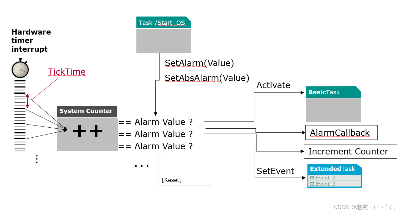
This is how you achieve a statement like "run Task_A every 10ms":
- Configure a GPT channel to generate an interrupt every 1ms.
- Configure the OS to use this interrupt to increment a counter,
SystemTimer. - Configure an OS Alarm,
Alarm_Task_A, tied toSystemTimer, with a cycle time of 10 ticks and an action to activateTask_A.
A Study of Software Implemented Fault Tolerance in ...
This paper provides context on AUTOSAR OS services and shows a practical example of how alarms are configured.
First, read the subsection 'Operating System' to understand the official relationship between Alarms and Counters. Then, look at 'Table 2: Os alarms scheduling...' to see a concrete example of how alarms are defined with cycle times and actions (like 'Set Event'). This demonstrates the OS-level configuration that the GPT driver will ultimately serve.
3. Implementing the GPT Driver APIs
As with other MCAL drivers, the GPT driver's behavior is determined by a generated configuration structure. The implementation involves reading this structure and programming the timer hardware accordingly.
Key APIs and Configuration
The central configuration container is GptChannelConfiguration. For each timer channel, you define:
GptChannelId: A unique numeric ID.GptChannelMode:GPT_CH_MODE_CONTINUOUSorGPT_CH_MODE_ONESHOT.GptChannelTickFrequency: The desired frequency in Hz, which determines the prescaler settings.GptNotification: A function pointer to the callback that will be invoked upon expiration. This is the key to OS integration. For the system tick, this will point to the OS's counter increment function.
Let's look at a conceptual implementation for the main functions.
Gpt_StartTimer
This function starts a specific channel counting towards a target value.
// In Gpt.c (driver implementation)

// Assumes Gpt_ConfigPtr points to the post-build configuration structure
void Gpt_StartTimer(Gpt_ChannelType Channel, Gpt_ValueType Value) {
    // 1. Validate inputs and driver state (DET checks)
    if (Gpt_DriverState != GPT_INITIALIZED) { /* report GPT_E_UNINIT */ return; }
    if (Channel >= MAX_GPT_CHANNELS) { /* report GPT_E_PARAM_CHANNEL */ return; }
    if (Value == 0 || Value > Gpt_ConfigPtr->ChannelConfig[Channel].MaxValue) {
        /* report GPT_E_PARAM_VALUE */
        return;
    }

    // 2. Get the specific channel configuration
    const Gpt_ChannelConfigType* chConf = &Gpt_ConfigPtr->ChannelConfig[Channel];

    // 3. Get the hardware timer base address corresponding to the channel
    // (This mapping is implementation-specific, often in a private config array)
    TIMER_RegDef_t* pTimer = Gpt_ChannelHardwareMap[Channel];

    // 4. Configure the hardware
    // Stop the timer before reconfiguring
    pTimer->CR1 &= ~TIMER_CR1_CEN;

    // Set the target value in the Auto-Reload Register (for up-counting timers)
    pTimer->ARR = Value;

    // Reset the counter to 0
    pTimer->CNT = 0;

    // Clear any pending interrupt flags
    pTimer->SR &= ~TIMER_SR_UIF;

    // Enable the timer
    pTimer->CR1 |= TIMER_CR1_CEN;

    // 5. Update the software state of the channel
    Gpt_ChannelState[Channel] = GPT_RUNNING;
}
The Interrupt Service Routine (ISR)
The ISR is the bridge between the hardware event and the configured software action.
// This is a conceptual ISR for a specific hardware timer
void TIMER2_UPDATE_ISR(void) {
    // This ISR is mapped to GptChannel_X
    Gpt_ChannelType Channel = GPT_CHANNEL_X;

    // 1. Get the channel configuration
    const Gpt_ChannelConfigType* chConf = &Gpt_ConfigPtr->ChannelConfig[Channel];
    TIMER_RegDef_t* pTimer = Gpt_ChannelHardwareMap[Channel];

    // 2. Check if the interrupt flag is set (important for shared ISRs)
    if ((pTimer->SR & TIMER_SR_UIF) != 0) {

        // 3. Clear the hardware interrupt flag to prevent re-entry
        // This is usually done by writing 0 to the flag bit
        pTimer->SR &= ~TIMER_SR_UIF;

        // 4. Handle mode-specific logic
        if (chConf->Mode == GPT_CH_MODE_ONESHOT) {
            // Stop the timer in one-shot mode
            pTimer->CR1 &= ~TIMER_CR1_CEN;
            Gpt_ChannelState[Channel] = GPT_EXPIRED;
        }
        // In continuous mode, the hardware automatically reloads, so no action is needed.

        // 5. If notifications are enabled for this channel, call the configured function
        if (Gpt_NotificationEnabled[Channel] == TRUE && chConf->NotificationCallback != NULL_PTR) {
            chConf->NotificationCallback();
        }
    }
}
Test your understanding!
You need to implement a timeout for an I2C transaction that should be 50ms. If the transaction does not complete in time, a function I2C_TimeoutHandler() should be called. How would you configure and use the GPT driver to achieve this?
Show answer
-
Configuration:
- Configure a GPT channel (e.g.,
GptChannel_I2C_Timeout) inGPT_CH_MODE_ONESHOT. - Set the
GptNotificationpointer for this channel to&I2C_TimeoutHandler. - Configure the channel's tick frequency to allow for a 50ms count (e.g., at 1kHz, the target value would be 50).
- Configure a GPT channel (e.g.,
-
Application Logic:
- Just before starting the I2C transaction, call
Gpt_EnableNotification(GptChannel_I2C_Timeout). - Then, call
Gpt_StartTimer(GptChannel_I2C_Timeout, 50). - If the I2C transaction completes successfully before the 50ms is up, call
Gpt_StopTimer(GptChannel_I2C_Timeout)to prevent the timeout handler from being called. - If the timer expires, the GPT ISR will call
I2C_TimeoutHandler().
- Just before starting the I2C transaction, call
4. GPT Predefined Timers
The AUTOSAR specification also defines a special category of timers called "Predefined Timers". These are not used for general-purpose notifications but rather provide a standardized, free-running time source for other BSW modules (e.g., the StbM - Synchronized Time-Base Manager).
Let's look at the specification for these special timers.
Read section 7.1, 'GPT Predef Timers'. Note the fixed tick durations (1µs, 100µs) and bit-widths. Also, see that they are started via Gpt_Init and read via a separate function, Gpt_GetPredefTimerValue.
Key characteristics of Predefined Timers:
- They are free-running up-counters that roll over automatically.
- They have standardized tick durations (e.g., 1µs, 100µs) and sizes.
- They are enabled via configuration and started automatically during
Gpt_Init. - They don't have notifications. Their values are read on-demand using the
Gpt_GetPredefTimerValueAPI.
5. Interview Corner
Q1: How does the GPT driver integrate with the AUTOSAR OS to schedule tasks?
A: The GPT driver provides the fundamental "system tick" for the OS. This is done by configuring a hardware timer channel in continuous mode to generate a periodic interrupt (e.g., every 1ms). The OS is configured with a Counter that is driven by this hardware timer. The ISR for the GPT interrupt calls an OS service (like IncrementCounter) to advance the OS counter. OS Alarms are then configured against this counter to trigger actions, such as activating a task, when the counter reaches a certain value. This creates the link from a hardware tick to scheduled task execution.
Q2: You're debugging an issue where a periodic 20ms task is sometimes delayed or skipped. You suspect the Gpt/OS integration. What are the key configuration parameters and code locations you would check?
A: I would investigate the entire chain from hardware to software:
- MCU Configuration: First, verify the Mcu clock configuration. Is the input clock to the timer peripheral correct? An incorrect system clock will scale all timer periods incorrectly.
- GPT Configuration: Check the configuration for the GPT channel used as the OS tick source.
- Is
GptChannelModeset toGPT_CH_MODE_CONTINUOUS? - Are the
GptChannelTickFrequencyand the target value inGpt_StartTimer(or equivalent OS setup) correctly calculated to produce the desired tick rate (e.g., 1ms)? - Is the
GptNotificationpointing to the correct OS counter-increment function?
- Is
- Interrupt Configuration (NVIC): Check the interrupt priority of the GPT system tick ISR. If it has too low a priority, it could be preempted by other, longer-running ISRs, causing tick interrupts to be delayed or missed. This is a common cause of jitter.
- OS Configuration: Check the OS Alarm configuration for the 20ms task. Is it correctly tied to the system counter with a cycle time of 20 ticks?
- Debugger Trace: Use a JTAG debugger like Lauterbach to set a tracepoint on the GPT ISR. I would verify that it is executing at a stable, periodic rate. I would also trace the OS task states to see if the target task is being preempted or blocked by a higher-priority task.
Q3: Explain the difference between a normal GPT channel and a GPT Predefined Timer.
A: A normal GPT channel is a flexible, general-purpose resource. It can be configured for one-shot or continuous mode, started and stopped dynamically via APIs (Gpt_StartTimer, Gpt_StopTimer), and is primarily used to trigger actions via notification callbacks. A GPT Predefined Timer is a specialized, free-running, high-resolution counter with a standardized tick rate (e.g., 1µs). It's started once at Gpt_Init and runs continuously. It does not have notifications; its purpose is to provide a common time reference that other modules can poll using Gpt_GetPredefTimerValue.
Conclusion
Today, you have learned how to implement one of the most essential MCAL drivers. The GPT driver is more than just a timer wrapper; it is the engine that drives the real-time behavior of the entire AUTOSAR system by providing the system tick to the Operating System.
Key Takeaways:
- The GPT driver abstracts hardware timers into channels that can run in one-shot or continuous mode.
- The core function in a real-time system is providing the periodic interrupt for the OS system tick.
- This is achieved by linking a continuous-mode GPT channel's notification to an OS function that increments an OS Counter. OS Alarms are then triggered by this counter to execute tasks.
- Driver implementation is configuration-driven, with APIs reading from generated structures to program hardware registers.
- The ISR is the critical link that must clear the hardware flag and invoke the configured software callback.
Next Lesson Preview:
We have now covered drivers for basic I/O (Port/Dio), core system services (Mcu), and timing (Gpt). Next, we will move on to communication peripherals. In the following lesson, we will tackle the SPI driver. You will learn to explain the AUTOSAR SPI driver model (Jobs, Sequences, Channels) and implement the Spi_SyncTransmit API, a more complex but powerful abstraction for serial data transfer.