Hello! Welcome back to your course on AUTOSAR MCAL Development.
In our previous lesson, we built the AUTOSAR GPT driver, establishing a crucial time base for the OS and learning how hardware timers enable software task scheduling. Now that we have mastered core MCU services and timing, we will shift our focus to communication peripherals, which are vital for any modern ECU.
Today's lesson addresses a cornerstone of on-board communication: the Serial Peripheral Interface (SPI). Your goal is to explain the AUTOSAR SPI driver model (Jobs, Sequences, Channels) and implement the Spi_SyncTransmit API. Given your extensive experience with communication stacks, we will focus on the specific abstraction model that AUTOSAR imposes on this common protocol, which is a key topic in driver development interviews.
1. The AUTOSAR SPI Abstraction Model
While SPI is a simple hardware protocol (MOSI, MISO, CLK, CS), real-world systems often involve multiple SPI devices on a shared bus, each with different communication requirements (e.g., different speeds, data formats, or priorities). AUTOSAR manages this complexity with a three-layered software abstraction: Channels, Jobs, and Sequences.
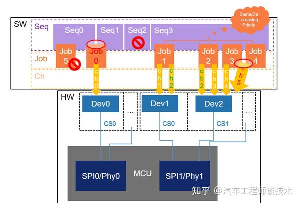
Let's break down this hierarchy, using the official AUTOSAR specification as our guide.
Specification of SPI Handler/Driver
To understand the model, we must first learn the precise definitions of its components from the AUTOSAR SPI Handler/Driver specification.
Please read the 'Definition' table in the 'Acronyms and abbreviations' section. Focus on the descriptions for Channel, Job, and Sequence.
Here is a summary of those key concepts:
-
Channel: A Channel is the most basic logical unit of data transmission. It represents a single, contiguous block of data to be sent or received. Key properties of a channel include:
- Data Buffers: The source and destination memory for the data. These can be managed internally by the SPI driver (Internal Buffer - IB) or provided by the application (External Buffer - EB).
- Data Width: The size of each data element (e.g., 8-bit, 16-bit).
- Transfer Order: Most Significant Bit (MSB) or Least Significant Bit (LSB) first.
-
Job: A Job groups one or more Channels that are all destined for the same external device, meaning they share the same physical settings and, most importantly, the same Chip Select (CS) line. A Job is considered an atomic unit of bus access; it cannot be interrupted by another Job on the same SPI bus. Its key properties are derived from the target external device:
- SPI Hardware Settings: Baud rate, clock polarity (CPOL), and clock phase (CPHA).
- Chip Select: The specific CS line to use and its active polarity.
- Priority: A priority level (0-3) used by the driver to schedule jobs.
-
Sequence: A Sequence is an ordered list of one or more Jobs. This is the unit of transmission that the application layer requests. A sequence can contain jobs that communicate with different external devices. A key property is:
- Interruptibility: A sequence can be configured as "interruptible," meaning a higher-priority sequence can preempt it between jobs.
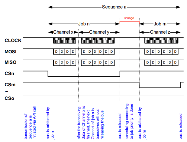
This model provides powerful control. For instance, you could define a high-priority sequence for reading critical sensor data that can interrupt a low-priority sequence that is writing to a log file on an external flash memory.
2. Configuring the SPI Driver Model
This abstract model is brought to life through configuration in an AUTOSAR authoring tool (like EB tresos, which you may be familiar with). The configuration generator then creates C structures that your driver implementation will use.
This TI AUTOSAR SPI Driver User Guide provides a practical look at how these concepts appear in a configuration tool.
Skim through section 4, 'Configuration'. Look at the tables for 'Spi external device configuration', 'Spi channels configuration', 'Spi job configuration', and 'Spi sequences configuration'. Note how a job references a device and channels, and how a sequence references jobs.
From the configuration, you can see the links:
- SpiExternalDevice: Defines physical properties like baud rate, clock settings, and the CS pin.
- SpiChannel: Defines data properties like buffer length and data width.
- SpiJob: Contains a reference to one
SpiExternalDeviceand a list of one or moreSpiChannelreferences. It also has a priority. - SpiSequence: Contains an ordered list of one or more
SpiJobreferences.
Your C driver code will not have hardcoded values. Instead, it will read these generated configuration structures to perform transmissions.
Test your understanding!
You need to send a 1-byte command to an SPI EEPROM, and then immediately read 32 bytes of data back from it. Both actions must happen without the Chip Select being de-asserted in between. How would you model this using Channels and Jobs?
Show answer
This would be modeled as a single Job directed at the EEPROM device. This Job would contain two Channels:
- Channel 1: A 1-byte channel for transmitting the command. The source buffer would contain the command byte. The destination buffer could be a
NULL_PTR. - Channel 2: A 32-byte channel for reading the data. The source buffer could be a
NULL_PTR(so the driver sends default data, typically0xFF, to clock the data out), and the destination buffer would point to where the 32 bytes of data should be stored.
Because both channels are in the same job, the Chip Select will remain asserted for the entire transaction, fulfilling the requirement. This job would then be placed in a Sequence to be initiated by the application.
3. Implementing Spi_SyncTransmit
Now let's translate this model into code. The Spi_SyncTransmit function is the blocking API used to execute a complete sequence. The function does not return until all jobs and channels in the sequence have been transmitted.
Specification of SPI Handler/Driver
Let's review the formal API definition for Spi_SyncTransmit from the AUTOSAR specification.
Locate section 8.3.11, 'Spi_SyncTransmit'. Pay close attention to its parameters, return values, and the description of its synchronous, re-entrant behavior. Note that it's only available for functionality Levels 0 and 2.
The function prototype is simple:Std_ReturnType Spi_SyncTransmit(Spi_SequenceType Sequence)
Here is a conceptual C implementation that shows how the driver would process this request. This assumes you have a Spi_ConfigPtr pointing to the post-build configuration data generated by the AUTOSAR toolchain.
// Assume Spi_Cfg.h defines the configuration structures
#include "Spi_Cfg.h"
#include "Spi.h"

// Assume this points to the active post-build configuration
extern const Spi_ConfigType* Spi_ConfigPtr;

// Global status variables
static Spi_StatusType Spi_DriverStatus = SPI_UNINIT;
static Spi_SeqResultType Spi_SequenceResults[SPI_MAX_SEQUENCES];

// --- API Implementation ---

Std_ReturnType Spi_SyncTransmit(Spi_SequenceType SequenceId) {
    // 1. --- Development Error Checks ---
    if (Spi_DriverStatus == SPI_UNINIT) {
        // Report DET error: SPI_E_UNINIT
        return E_NOT_OK;
    }
    if (SequenceId >= Spi_ConfigPtr->NumSequences) {
        // Report DET error: SPI_E_PARAM_SEQUENCE
        return E_NOT_OK;
    }
    // Check if another synchronous transfer is already in progress on the same HW bus
    // (requires tracking HW unit status)
    if (Spi_DriverStatus == SPI_BUSY) {
        // Report DET error: SPI_E_SEQ_IN_PROCESS
        return E_NOT_OK;
    }

    // 2. --- Set Driver and Sequence Status ---
    Spi_DriverStatus = SPI_BUSY;
    Spi_SequenceResults[SequenceId] = SPI_SEQ_PENDING;

    // 3. --- Main Processing Loop ---
    const Spi_SequenceConfigType* pSeqConf = &Spi_ConfigPtr->SequenceConfig[SequenceId];

    // Iterate through all Jobs in the Sequence
    for (uint16_t i = 0; i < pSeqConf->NumJobs; ++i) {
        Spi_JobType JobId = pSeqConf->JobAssignment[i];
        const Spi_JobConfigType* pJobConf = &Spi_ConfigPtr->JobConfig[JobId];
        const Spi_ExternalDeviceConfigType* pDevConf = pJobConf->DeviceAssignment; // Pointer to device settings

        // A. --- Configure SPI Peripheral for this Job ---
        // (Implementation specific register access)
        // e.g., SetBaudRate(pDevConf->Baudrate);
        // e.g., SetClockPhaseAndPolarity(pDevConf->Cpha, pDevConf->Cpol);
        // e.g., SetHwUnit(pJobConf->HwUnit);

        // B. --- Assert Chip Select ---
        // e.g., Dio_WriteChannel(pDevConf->CsPinId, pDevConf->CsPolarity);

        // C. --- Iterate through all Channels in the Job ---
        for (uint16_t j = 0; j < pJobConf->NumChannels; ++j) {
            Spi_ChannelType ChannelId = pJobConf->ChannelAssignment[j];
            const Spi_ChannelConfigType* pChanConf = &Spi_ConfigPtr->ChannelConfig[ChannelId];

            // Iterate through the data in the channel
            for (Spi_NumberOfDataType k = 0; k < pChanConf->Length; ++k) {
                // Get data to transmit
                Spi_DataBufferType txData = (pChanConf->TxBuffer != NULL_PTR) ? pChanConf->TxBuffer[k] : pChanConf->DefaultData;

                // --- Polling-based transmission ---
                // Wait until Transmit buffer is empty (e.g., while(!(SPI_SR & TXE_FLAG));)

                // Write data to SPI Data Register (e.g., SPI_DR = txData;)

                // Wait until Receive buffer is full (e.g., while(!(SPI_SR & RXNE_FLAG));)

                // Read data from SPI Data Register
                Spi_DataBufferType rxData = SPI_DR;

                // Store received data if buffer is provided
                if (pChanConf->RxBuffer != NULL_PTR) {
                    pChanConf->RxBuffer[k] = rxData;
                }
            }
        }

        // D. --- De-assert Chip Select ---
        // (Could be delayed based on configuration SpiCsBehavior == CS_KEEP_ASSERTED)
        // e.g., Dio_WriteChannel(pDevConf->CsPinId, !pDevConf->CsPolarity);
    }

    // 4. --- Finalize Status and Return ---
    Spi_SequenceResults[SequenceId] = SPI_SEQ_OK;
    Spi_DriverStatus = SPI_IDLE;

    return E_OK;
}
This implementation demonstrates the core logic: it unpacks the configuration hierarchy (Sequence -> Job -> Channel) and executes the data transfers in a polling, blocking manner, which is the essence of Spi_SyncTransmit.
4. Interview Corner
Q1: Can you explain the AUTOSAR SPI driver's Channel, Job, and Sequence model? What problem does this abstraction solve?
A: The model is a three-tier hierarchy. A Channel is a buffer of data. A Job is a group of channels sent to a single device with a single Chip Select assertion, making it an atomic hardware access. A Sequence is a list of jobs that the application can request to be transmitted. This model solves the problem of managing access to a shared SPI bus with multiple devices, each potentially having different communication parameters (speed, clock mode) and priorities. It allows the application to define complex, multi-device transactions while the driver handles the low-level scheduling, prioritization, and hardware configuration.
Q2: You need to implement a driver for a new SPI device that requires a 10µs delay between asserting Chip Select and the first clock edge. Where in the AUTOSAR SPI configuration and driver implementation would you handle this?
A: This timing requirement belongs to the physical characteristics of the device. Therefore, it would be configured in the SpiExternalDevice container, likely as a parameter like SpiTimeCs2Clk. In the C implementation of Spi_SyncTransmit, after asserting the Chip Select (Dio_WriteChannel), I would insert a delay function. This delay function would be called right before starting the channel data loop for the job. The duration of the delay would be read from this SpiTimeCs2Clk parameter in the job's associated device configuration structure.
Q3: Describe the key differences between Spi_SyncTransmit and Spi_AsyncTransmit. In a system with an RTOS, which one would you prefer for transmitting a large 2KB data packet and why?
A: Spi_SyncTransmit is a blocking (synchronous) function. It doesn't return control to the caller until the entire sequence is transmitted, typically using a busy-wait or polling loop. Spi_AsyncTransmit is non-blocking (asynchronous). It initiates the transfer, often using interrupts or DMA, and returns immediately. The completion of the transfer is signaled later via a callback notification.
For a large 2KB packet in an RTOS environment, I would strongly prefer Spi_AsyncTransmit. Using Spi_SyncTransmit would block the calling task for a long time, consuming CPU cycles in a polling loop and preventing other tasks from running. This wastes CPU time and can easily lead to missed deadlines for other tasks. An asynchronous transfer allows the CPU to perform other work or enter a low-power state while the SPI peripheral and DMA controller handle the transfer in the background, making the system much more efficient.
Conclusion
Today we have dissected the sophisticated abstraction layer that AUTOSAR places on top of the simple SPI protocol. You've learned how this model provides a flexible and powerful way to manage complex communication scenarios.
Key Takeaways:
- The AUTOSAR SPI driver model is built on a hierarchy of Sequences -> Jobs -> Channels.
- A Channel is a data buffer, a Job is an atomic transaction with one device (one CS), and a Sequence is the application-level request.
- This model allows for managing shared buses, different device settings, and prioritization.
Spi_SyncTransmitis a blocking API that iterates through the configured jobs and channels in a sequence, performing the transmission in a polling manner.- The driver's C implementation is configuration-driven, reading from generated structures to control the hardware.
Next Lesson Preview:
We will continue our exploration of communication drivers by moving to another protocol that is central to your work experience: CAN. In the next lesson, you will learn to implement the AUTOSAR Can driver, including initialization, transmission (Can_Write), and reception indication to the CanIf module. This will provide more insight into how MCAL drivers interface with the layers above them.