Hello! Welcome back to your AUTOSAR MCAL development course.
In our last lesson, we dissected the AUTOSAR SPI driver, focusing on the Channel/Job/Sequence abstraction model and the implementation of Spi_SyncTransmit. This gave us a solid foundation in how AUTOSAR creates structured, configurable interfaces for hardware peripherals.
Today, we turn our attention to a protocol that is central to your expertise: CAN. Your learning goal is to implement the AUTOSAR Can driver, including initialization, transmission (Can_Write), and reception indication to CanIf.
Given your extensive background with the AUTOSAR communication stack, you're well-versed in the roles of the COM module, PDU Router, and CanIf from the perspective of an integrator and system designer. This lesson will take you to the other side of the CanIf API—into the MCAL layer, where the Can driver directly commands the silicon. Mastering this is a crucial skill for low-level driver development interviews.
1. Architectural Context: The Role of the CAN Driver
Before we write any code, it's essential to pinpoint the CAN driver's exact position and responsibility within the AUTOSAR architecture. The data flow from the application to the physical bus is a multi-stage journey through several BSW modules.
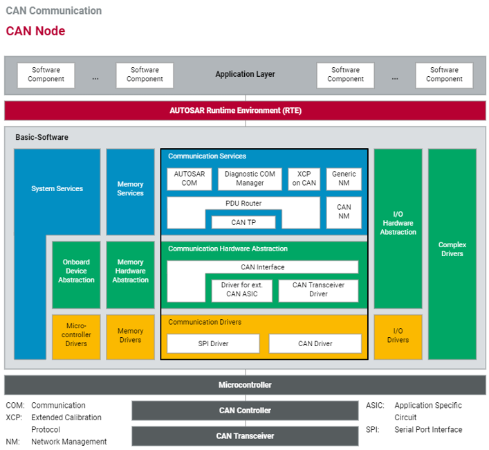
As you know, a signal originating in a Software Component (SW-C) is passed through the RTE, packaged into an I-PDU by the COM module, and routed by the PDU Router to the appropriate interface module, in this case, CanIf. This is where our focus begins.
To get a dynamic overview of this entire flow, let's watch a short video.
The following clip from ANCIT Technical Videos provides a great animated walkthrough of the AUTOSAR communication stack, reinforcing how the layers interact.
Please watch the two segments on data flow and the CanIf/Can driver interaction. The first part (20:01 - 28:09) explains the journey of a signal from the RTE down to the hardware, defining terms like IPDU, NPDU, and LPDU. Pay close attention to the role of each module in adding information. The second part (47:34 - 55:25) details the specific responsibilities of the CanIf and Can drivers. Focus on how CanIf maps PDUs to hardware objects and how the Can driver executes the hardware access.
As the video explains, the key responsibilities are split:
-
CAN Interface (CanIf): This is a hardware-independent module. Its primary roles are:
- Mapping PDUs from the PDU Router to the correct CAN controller and a specific hardware object (like a transmit or receive mailbox).
- Providing a unified API to upper layers for transmission (
CanIf_Transmit) and reception notifications (CanIf_RxIndication,CanIf_TxConfirmation). - Managing the state of the CAN controllers (
CAN_CS_STARTED,CAN_CS_STOPPED).
-
CAN Driver (Can): This is the hardware-dependent MCAL module we are implementing. It is responsible for:
- Initializing the CAN controller hardware (e.g., bit timing, message buffers).
- Providing the API (
Can_Init,Can_Write) thatCanIfcalls to interact with the hardware. - Handling hardware interrupts (Rx, Tx, Bus-Off) and notifying
CanIfvia callbacks. - Abstracting the details of hardware registers.
The central concept bridging these two layers is the Hardware Object Handle (HOH). CanIf deals with abstract HOHs, while the Can driver's configuration maps each HOH to a physical resource (e.g., Message Buffer #5 on CAN Controller 1).
2. CAN Driver Initialization
Like any driver, the first step is initialization. The Can_Init function is called once at startup by the ECU State Manager (EcuM) to prepare the CAN hardware for operation.
Let's look at the formal definition.
The AUTOSAR SWS for the CAN Driver specifies the exact behavior of Can_Init. This is the standard all implementations must follow.
Please read sections 7.3 'CAN Controller State Machine' and 8.3.1.1 'Can_Init'. Focus on understanding that Can_Init moves all controllers to the CAN_CS_STOPPED state and what that state entails.
The key tasks of Can_Init are:
- Safety Check: Ensure the driver is in the
CAN_UNINITstate. - Global Configuration: Configure hardware settings that apply to the entire CAN peripheral unit (e.g., global control registers, clock sources).
- Per-Controller Configuration: For each CAN controller managed by the driver:
- Set the bit timing registers based on the parameters in the baud rate configuration (
CanControllerBaudrateConfig) to achieve the desired bus speed. - Initialize the hardware message objects (mailboxes/buffers) for both transmission (Tx) and reception (Rx) as defined in the
CanHardwareObjectconfiguration. For Rx objects, this includes setting up the acceptance filters (ID and mask). - Disable all CAN interrupts initially.
- Transition the controller into the
CAN_CS_STOPPEDstate. It is now configured but not yet participating on the bus.
- Set the bit timing registers based on the parameters in the baud rate configuration (
- State Transition: Set the global driver state to
CAN_READY.
Here is a conceptual implementation of Can_Init:
#include "Can.h"
#include "Can_Cfg.h" // Assumes this contains generated configuration

// Global variable to hold driver state
static Can_StatusType Can_DriverStatus = CAN_UNINIT;

// API Implementation
void Can_Init(const Can_ConfigType* Config) {
    // 1. --- Development Error & State Checks ---
    if (Config == NULL_PTR) {
        // Report DET: CAN_E_PARAM_POINTER
        return;
    }
    if (Can_DriverStatus != CAN_UNINIT) {
        // Report DET: CAN_E_TRANSITION
        return;
    }

    // Store the configuration pointer
    Can_ConfigPtr = Config;

    // 2. --- Loop through all configured CAN controllers ---
    for (uint8_t ControllerId = 0; ControllerId < CAN_CONTROLLER_COUNT; ++ControllerId) {
        const Can_ControllerConfigType* pControllerCfg = &Config->ControllerConfig[ControllerId];

        // Get base address of the CAN controller's registers
        CAN_Reg_Base* pCanReg = pControllerCfg->BaseAddress;

        // A. Enter initialization mode (HW-specific)
        pCanReg->CTRL |= CAN_CTRL_INIT_MODE;
        // Wait for ack bit...

        // B. Configure Baud Rate (Bit Timing)
        const Can_ControllerBaudrateConfigType* pBaudrateCfg = &pControllerCfg->DefaultBaudrate;
        pCanReg->BIT_TIMING_REG = 0; // Clear register
        pCanReg->BIT_TIMING_REG |= (pBaudrateCfg->PropSeg << PROP_SEG_SHIFT);
        pCanReg->BIT_TIMING_REG |= (pBaudrateCfg->Seg1 << SEG1_SHIFT);
        pCanReg->BIT_TIMING_REG |= (pBaudrateCfg->Seg2 << SEG2_SHIFT);
        pCanReg->BIT_TIMING_REG |= (pBaudrateCfg->Sjw << SJW_SHIFT);
        pCanReg->PRESCALER_REG = pBaudrateCfg->Prescaler;

        // C. Configure Hardware Objects (Message Buffers)
        for (uint16_t HwObjId = 0; HwObjId < pControllerCfg->NumHwObjects; ++HwObjId) {
            const Can_HardwareObjectType* pHwObjCfg = &pControllerCfg->HwObjectConfig[HwObjId];

            if (pHwObjCfg->ObjectType == CAN_OBJECT_TYPE_RECEIVE) {
                // Configure Rx filter for this message object
                CAN_MsgObj* pMsgObj = &pCanReg->MsgObjects[pHwObjCfg->HwObjectId];
                pMsgObj->MASK = pHwObjCfg->IdMask;
                pMsgObj->ID   = pHwObjCfg->IdValue;
                pMsgObj->CTRL = MSG_CTRL_RX_ENABLE; // Mark as Rx object
            }
            // Tx objects are typically configured just before transmission
        }

        // D. Leave initialization mode -> moves controller to STOPPED state
        pCanReg->CTRL &= ~CAN_CTRL_INIT_MODE;
    }

    // 3. --- Set driver status to ready ---
    Can_DriverStatus = CAN_READY;
}
After Can_Init completes, a call to Can_SetControllerMode(ControllerId, CAN_T_START) is required to make a specific controller participate on the bus.
3. Transmitting a CAN Message
The Can_Write function is the workhorse for transmission. It is called by CanIf to send a single L-PDU.
CAN driver user guide, TRAVEO™ T2G family
Let's examine the API definition for Can_Write in a practical driver user guide from Infineon's TRAVEO™ T2G family.
Please read section 7.4.6, 'Can_Write'. Pay close attention to the parameters Hth and PduInfo, the possible return values (CAN_OK, CAN_NOT_OK, CAN_BUSY), and the list of potential development errors.
The function signature is:Can_ReturnType Can_Write(Can_HwHandleType Hth, const Can_PduType* PduInfo)
Here's how it works:
- Parameter Validation: The function first performs several checks (DET): Is the driver initialized? Is the
Htha valid, configured transmit handle? Is thePduInfopointer valid? Is the DLC valid? - Hardware Object Lookup: The
Hthis used to find the corresponding physical hardware transmit object (mailbox). This mapping is defined in the configuration. - Buffer Availability Check: The driver checks a status bit to see if this specific hardware transmit object is free. This is a crucial step. If the object is still busy with a previous transmission, the function must immediately return
CAN_BUSY. It must not wait. - Data Copy: If the buffer is free, the driver copies the CAN ID, DLC, and the payload data (from
PduInfo->sdu) into the registers of the hardware transmit object. - Trigger Transmission: The driver sets a "transmit request" bit in a control register for that hardware object. The CAN peripheral then takes over, arbitrates for the bus, and sends the frame.
- Return Success: The function returns
CAN_OKtoCanIf.
Conceptual implementation:
Can_ReturnType Can_Write(Can_HwHandleType Hth, const Can_PduType* PduInfo) {
    // 1. --- Development Error Checks ---
    if (Can_DriverStatus == CAN_UNINIT) { /* Report DET, return CAN_NOT_OK */ }
    if (Hth >= CAN_TX_HW_OBJECT_COUNT) { /* Report DET, return CAN_NOT_OK */ }
    if (PduInfo == NULL_PTR || PduInfo->sdu == NULL_PTR) { /* Report DET, return CAN_NOT_OK */ }
    if (PduInfo->length > 8) { /* Report DET (for classic CAN), return CAN_NOT_OK */ }

    // 2. --- Find the corresponding HW object ---
    const Can_HardwareObjectType* pHwObjCfg = &Can_ConfigPtr->HwObjectConfig[Hth];
    CAN_Reg_Base* pCanReg = Can_ConfigPtr->ControllerConfig[pHwObjCfg->ControllerRef].BaseAddress;
    CAN_MsgObj* pMsgObj = &pCanReg->MsgObjects[pHwObjCfg->HwObjectId];

    // 3. --- Check if hardware transmit buffer is busy ---
    if ((pMsgObj->CTRL & MSG_CTRL_TX_PENDING) != 0) {
        return CAN_BUSY; // HW object is not free
    }

    // 4. --- Copy PDU data to hardware registers ---
    pMsgObj->ID = PduInfo->id;
    pMsgObj->DLC = PduInfo->length;
    for (uint8_t i = 0; i < PduInfo->length; ++i) {
        pMsgObj->DATA[i] = PduInfo->sdu[i];
    }

    // 5. --- Trigger Transmission ---
    pMsgObj->CTRL |= MSG_CTRL_TX_REQUEST;

    return CAN_OK;
}
Test your understanding!
The CanIf layer calls Can_Write and receives a CAN_BUSY return value. What should the CanIf layer do next? Should it immediately call Can_Write again?
Show answer
No, it should not immediately retry. The CAN_BUSY status indicates that the hardware resource is temporarily unavailable. The standard AUTOSAR behavior for CanIf is to drop the transmit request. If buffering is required, it is typically handled at a higher layer, like the AUTOSAR COM module, which can be configured with transmission modes (e.g., periodic with repetitions) that will try to send the message again later. The MCAL driver itself is designed to be lean and non-blocking.
4. Receiving a CAN Message and Notifying CanIf
Reception is the inverse of transmission and is almost always interrupt-driven for efficiency.
The process is as follows:
- A frame arrives on the bus.
- The CAN controller's hardware acceptance filter checks if the incoming CAN ID matches any of the rules configured for the Rx message objects.
- If a match is found, the hardware automatically stores the message (ID, DLC, data) into the corresponding message object.
- The hardware then sets an interrupt flag for that message object or a general "message received" flag.
- This triggers the microcontroller's interrupt controller, which invokes the
Candriver's configured Interrupt Service Routine (ISR). - Inside the ISR, the driver identifies which message object received data, reads the PDU information from the hardware registers, and clears the interrupt flag.
- Finally, the
Candriver's ISR calls theCanIf_RxIndication()function, passing the handle of the hardware object and a pointer to the PDU info.

Let's look at the standard signature for this callback.
The CanIf_RxIndication function is the standard upward-facing interface for received messages. It's implemented by CanIf and called by the Can driver.
Review section 8.6.1 'Mandatory Interfaces'. Find the entry for CanIf_RxIndication to see its role in the driver's expected environment.
A conceptual ISR might look like this:
// This is the function registered in the vector table for CAN interrupts
void CAN_RX_ISR(void) {
    // 1. --- Determine which controller and message object caused the interrupt ---
    // This logic is highly hardware-specific. It might involve reading an interrupt status register.
    uint8_t ControllerId = FindInterruptSourceController();
    uint16_t HwObjectId = FindInterruptSourceMailbox(ControllerId);

    const Can_HardwareObjectType* pHwObjCfg = &Can_GetHwObjectConfig(ControllerId, HwObjectId);
    CAN_Reg_Base* pCanReg = Can_GetControllerBaseAddress(ControllerId);
    CAN_MsgObj* pMsgObj = &pCanReg->MsgObjects[HwObjectId];

    // 2. --- Prepare PDU info to pass up to CanIf ---
    Can_PduType ReceivedPdu;
    uint8_t SduBuffer[8]; // A temporary buffer in the ISR stack

    ReceivedPdu.id = pMsgObj->ID;
    ReceivedPdu.length = pMsgObj->DLC;
    ReceivedPdu.sdu = SduBuffer;

    // Copy data from hardware buffer to temporary ISR buffer
    for (uint8_t i = 0; i < ReceivedPdu.length; ++i) {
        SduBuffer[i] = pMsgObj->DATA[i];
    }

    // Structure required by modern AUTOSAR CanIf_RxIndication
    Can_HwType Mailbox;
    Mailbox.CanId = ReceivedPdu.id;
    Mailbox.Hoh = pHwObjCfg->Hoh; // Pass the abstract handle back up
    Mailbox.ControllerId = pHwObjCfg->ControllerRef;

    // 3. --- Clear the interrupt flag in hardware ---
    pMsgObj->CTRL &= ~MSG_CTRL_RX_INT_PENDING;

    // 4. --- Call the upper layer's notification function ---
    CanIf_RxIndication(&Mailbox, &ReceivedPdu);
}
This completes the journey. The data has moved from the physical bus all the way back up to the ECU Abstraction Layer, with the Can driver acting as the crucial hardware-to-software bridge.
5. Interview Corner
Q1: Walk me through the Can_Write function. What are its key parameters, what checks does it perform, and what are its possible return values?
A: Can_Write takes a Can_HwHandleType (Hth) and a pointer to a Can_PduType. The Hth identifies the hardware transmit resource. The function checks for uninitialization, invalid handles, and invalid PDU parameters. Crucially, it checks if the hardware object for the Hth is busy. If it is, it returns CAN_BUSY. If free, it copies the PDU data to the hardware, triggers the transmission, and returns CAN_OK. If a development error is found, it returns CAN_NOT_OK.
Q2: What is the purpose of hardware acceptance filtering in a CAN controller, and where is it configured in the AUTOSAR Can driver model?
A: Acceptance filtering is a hardware mechanism that automatically filters incoming CAN messages based on their ID. It allows the microcontroller to ignore irrelevant traffic on the bus, significantly reducing CPU load as no software intervention is needed for unwanted messages. In AUTOSAR, the filter masks and values are configured within the CanHardwareObject container for objects of type RECEIVE. These settings are then written to the CAN controller's filter registers by the Can_Init function.
Q3: Contrast the Can driver model with the Spi driver's Channel/Job/Sequence model. Why is the CAN driver's API simpler (e.g., just Can_Write with an Hth)?
A: The SPI model is complex because SPI is a master-driven, point-to-point-like protocol on a potentially shared bus. A single transaction can involve multiple data exchanges (channels) with one device (a job) and may need to be sequenced with transactions to other devices. The Can driver model is simpler because CAN is a message-based, multi-master broadcast protocol. Each transmission is an atomic, self-contained message. The CanIf and PduR layers have already determined which PDU goes to which CAN controller. The Can driver's only job is to take this resolved L-PDU and put it into the correct hardware transmit buffer, identified by the Hth. There's no concept of sequencing multiple messages into a single hardware transaction.
Conclusion
In this lesson, we bridged the gap between your high-level AUTOSAR knowledge and the low-level implementation details of the MCAL. We've seen how the Can driver executes the commands from CanIf to initialize the hardware, transmit messages, and handle incoming data via interrupts.
Key Takeaways:
- The
Candriver is the hardware-dependent MCAL layer responsible for controlling the CAN peripheral. Can_Initconfigures the controller's core settings, including bit timing and acceptance filters, and places it in theSTOPPEDstate.Can_Writeis a non-blocking function that attempts to place a PDU into a hardware transmit object. It returnsCAN_BUSYif the hardware is not ready, delegating buffering strategy to upper layers.- Reception is an interrupt-driven process where the ISR reads data from hardware and notifies the upper layer by calling the
CanIf_RxIndicationcallback function.
Next Lesson Preview:
Having covered several key drivers, we will now shift our focus from peripheral control to system-level architecture and security. In the next lesson, we will begin our exploration of advanced ARM features by describing the ARM TrustZone architecture, a hardware foundation for creating isolated Secure and Non-Secure execution environments, which is critical for modern automotive security.