Hello! Welcome back to our course on AUTOSAR MCAL Development.
In our previous lesson, we demystified the ARXML files that form the backbone of AUTOSAR configuration. We learned how to analyze an ECU Configuration Description file to find the specific parameters that define the behavior of MCAL drivers. You now understand that these parameters are the "source of truth" and are typically defined as pre-compile time, meaning they are baked into the generated C code.
Today, we will bring that concept to life. We'll bridge the gap between the abstract configuration and the concrete C code by focusing on two of the most fundamental MCAL drivers: Port and Digital I/O (Dio). Our learning outcome is to implement core functionality for the AUTOSAR Port and Dio drivers based on a configuration structure. This lesson will be very practical, directly reflecting the kind of hands-on driver work you'd encounter in your target role and building upon your extensive AUTOSAR experience.
1. The Separation of Concerns: Port vs. Dio
A common point of confusion for newcomers is understanding why two separate drivers are needed for GPIO. The answer lies in a clean architectural principle: separating hardware initialization from runtime operation.
-
The Port Driver (
Port): Its sole responsibility is to configure the physical properties of the microcontroller's pins. This is a one-time setup task performed during ECU initialization. It answers questions like:- Is this pin an input or an output?
- Should it be connected to the GPIO module, the SPI peripheral, or the CAN controller? (This is called multiplexing).
- Does it need an internal pull-up or pull-down resistor?
- What should its electrical drive strength or slew rate be?
-
The Dio Driver (
Dio): This driver is used for runtime I/O operations on pins that have already been configured as GPIOs by the Port driver. It provides a simple API to:- Read the digital state of an input pin (
STD_HIGHorSTD_LOW). - Write a digital state to an output pin.
- Flip the state of an output pin.
- Read the digital state of an input pin (
This architectural separation is powerful. The Port driver deals with complex, chip-specific hardware registers for pin configuration, while the Dio driver provides a simple, abstract, and portable API for the application layers to use.
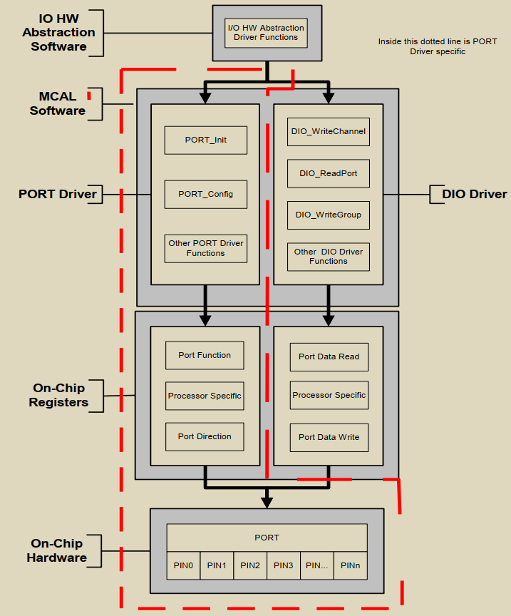
To solidify this concept, let's review a concise summary.
The following resource, 'getting started with mcal', provides a clear and direct explanation of the distinction between the Port and Dio modules.
Please read slide 26, titled 'Background: MCAL Modules Used for GPIO'. Focus on how it defines the roles of PORT (configures port pins) and DIO (reading and writing GPIO data).
2. Implementing the Port Driver: Setting the Stage
The Port driver's primary function is Port_Init(). This function is the bridge between the configuration you created (as we discussed in the last lesson) and the microcontroller's hardware registers.
The Configuration Structure
When you configure the pins in an AUTOSAR tool (like EB Tresos), the code generator doesn't just produce ARXML. It also creates C source and header files (Port_Cfg.c and Port_Cfg.h). The most important artifact is a configuration structure, typically defined as a const C struct. It might look conceptually like this:
// This is a conceptual example, actual structure varies by vendor
typedef struct {
    uint16_t  pinId;       // A symbolic ID for the pin
    uint32_t  pcrValue;    // The value to write to the Pin Control Register
    uint8_t   direction;   // Initial direction (IN/OUT)
    // ... other parameters like pull-up/down, initial level, etc.
} Port_PinConfigType;

typedef struct {
    const Port_PinConfigType* PinConfigs; // Pointer to an array of pin configurations
    uint16_t                  NumberOfPins; // Total number of pins to configure
} Port_ConfigType;

// This structure is generated into Port_Cfg.c and filled with values from ARXML
extern const Port_ConfigType PortConfigSet_0;
The Port_Init Function
The Port_Init function, which is part of the vendor-provided MCAL code, takes a pointer to this generated structure. Its implementation is straightforward: it iterates through the array of pin configurations and writes the specified values directly to the microcontroller's hardware registers.
/*
 * Service for PORT initialization.
 * SWS_Port_00071: The function Port_Init shall initialize all pins with the values of the
 * structure referenced by the parameter ConfigPtr.
 */
void Port_Init(const Port_ConfigType* ConfigPtr) {
    if (ConfigPtr == NULL) {
        // Handle error: null configuration pointer
        return;
    }

    // Iterate through all the pins defined in the configuration structure
    for (uint16_t i = 0; i < ConfigPtr->NumberOfPins; i++) {

        // Get the specific pin's configuration
        const Port_PinConfigType* pinConf = &ConfigPtr->PinConfigs[i];

        // 1. Get the base address of the SIUL2 (System Integration Unit Lite 2) or equivalent
        //    peripheral responsible for pin configuration.
        // 2. Calculate the address of the specific Multiplexed Signal Configuration Register (MSCR)
        //    for this pin using its ID.
        // 3. Write the pre-calculated configuration value from the struct into the register.
        //    This single write configures multiplexing, slew rate, pull resistors, etc.

        // Example (conceptual):
        // volatile uint32_t* mscr_register = (volatile uint32_t*)(SIUL2_BASE_ADDR + pinConf->pinId * 4);
        // *mscr_register = pinConf->pcrValue;
    }
}
Port_Init is called once during the ECU startup sequence, after the MCU clocks are stable (Mcu_Init) but before any peripherals that use these pins are initialized.
3. Implementing the Dio Driver: Runtime Control
Once Port_Init has run, any pin configured as a GPIO is ready for use by the Dio driver.
Symbolic Names
The Dio configuration process generates a header file (Dio_Cfg.h) containing #define macros. These macros create symbolic, human-readable names for each GPIO channel, mapping them to a unique numerical ID that the Dio driver functions understand.
// Generated in Dio_Cfg.h
#define DioConf_DioChannel_LED_GREEN      ((Dio_ChannelType)101)
#define DioConf_DioChannel_BUTTON_STATUS  ((Dio_ChannelType)2)
Using these symbolic names instead of raw numbers (101) makes the application code readable and less prone to errors.
Core Functions
The two main Dio functions are Dio_ReadChannel and Dio_WriteChannel.
/*
 * SWS_Dio_00078: Returns the value of the specified DIO channel.
 */
Dio_LevelType Dio_ReadChannel(Dio_ChannelType ChannelId) {
    // 1. Use the ChannelId to look up the physical port and pin number.
    //    This lookup might involve a generated array or some bit manipulation.
    //    For example, ChannelId 101 might map to Port G, Pin 5.

    // 2. Read the hardware's GPIO Port Data Input Register for that port.
    //    uint32_t port_value = GPDI_REGISTER_FOR_PORT_G;

    // 3. Isolate the bit corresponding to the pin number.
    //    if ((port_value & (1U << 5)) != 0) {
    //        return STD_HIGH;
    //    } else {
    //        return STD_LOW;
    //    }
}

/*
 * SWS_Dio_00079: Service to set a level of a channel.
 */
void Dio_WriteChannel(Dio_ChannelType ChannelId, Dio_LevelType Level) {
    // 1. Look up the physical port and pin number from ChannelId.

    // 2. Atomically set or clear the bit in the hardware's GPIO Port Data Output Register.
    //    Using atomic operations (or special set/clear registers if available) is critical
    //    to avoid race conditions in a multi-threaded or interrupt-driven environment.
    //    This prevents a read-modify-write operation on the whole port from being interrupted.

    //    if (Level == STD_HIGH) {
    //        GPDO_SET_REGISTER_FOR_PORT_G = (1U << 5);
    //    } else {
    //        GPDO_CLEAR_REGISTER_FOR_PORT_G = (1U << 5);
    //    }
}
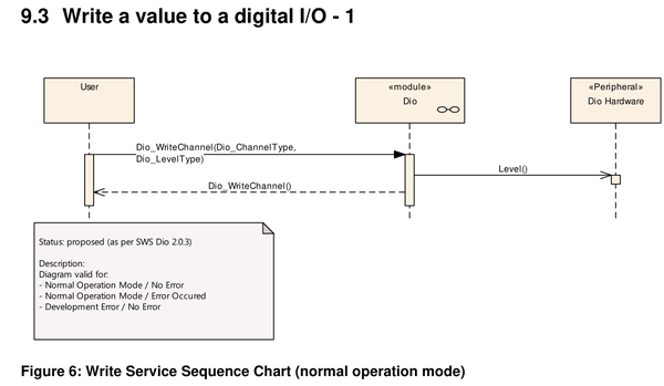
Test your understanding!
You need to implement a function void set_brake_light(bool is_on) that controls an LED connected to a pin named BRAKE_LIGHT_PIN in your AUTOSAR configuration. Which AUTOSAR functions would you call inside your function, and in what order? What other initialization function must have been called before your set_brake_light function can work correctly?
Show answer
Inside your function, you would call Dio_WriteChannel. The ChannelId would be the generated symbolic name, DioConf_DioChannel_BRAKE_LIGHT_PIN, and the Level would be STD_HIGH if is_on is true, or STD_LOW otherwise.
void set_brake_light(bool is_on) {
    if (is_on) {
        Dio_WriteChannel(DioConf_DioChannel_BRAKE_LIGHT_PIN, STD_HIGH);
    } else {
        Dio_WriteChannel(DioConf_DioChannel_BRAKE_LIGHT_PIN, STD_LOW);
    }
}
Critically, for this to work, the Port_Init() function must have been called at startup to configure the BRAKE_LIGHT_PIN as a GPIO output.
4. A Practical Example: Blinking an LED
Let's trace the full lifecycle from configuration to application code using a simple "read a switch, control an LED" example.
Getting Started with AUTOSAR MCAL
This guide from NXP provides a complete walkthrough of configuring the Port and Dio drivers in a tool and then using them in an application. It's a perfect practical example.
Please review slide 61, 'Add Dio code to main function in main.c'. This snippet shows exactly how the generated configuration (PortConfigSet_0 and DioConf_DioChannel_...) is used by the application code.
Let's analyze the code from the guide:
// In main.c, before the main loop
// This call executes the logic we discussed in Section 2. It configures all pins,
// including the switch input and the LED output.
Port_Init(&PortConfigSet_0);

// Inside the main loop
Level_Switch2 = Dio_ReadChannel((Dio_ChannelType)DioConf_DioChannel_Switch2);

if (Level_Switch2 == 1) {
    // Switch is pressed, turn LED off
    Dio_WriteChannel((Dio_ChannelType)DioConf_DioChannel_LED4, 1);
} else {
    // Switch is not pressed, turn LED on
    Dio_WriteChannel((Dio_ChannelType)DioConf_DioChannel_LED4, 0);
}
This simple example perfectly encapsulates the entire process:
- Configure: The user defines
Switch2andLED4in a configuration tool. - Generate: The tool produces
PortConfigSet_0and theDioConf_...symbolic names. - Initialize: The application calls
Port_Init()once to set up the hardware. - Execute: The application uses the
Dio_ReadChannelandDio_WriteChannelAPIs in its runtime logic.
Interview Corner
Q1: What is the fundamental difference between the AUTOSAR Port and Dio drivers?
A: The Port driver is for initialization. It configures the hardware properties of a pin, like its function (multiplexing), direction, and electrical characteristics (pull-ups/downs). It's typically used only once at startup via Port_Init. The Dio driver is for runtime I/O. It reads and writes digital logic levels on pins that have already been configured as GPIOs by the Port driver.
Q2: You're debugging an issue where an LED connected to a pin is not turning on. What are the first things you would check in the software, considering both the Port and Dio configurations?
A: I would follow the signal flow. First, I'd check the Port driver configuration for that pin. Is it correctly configured as an output (PORT_PIN_OUT)? Then, in the application code, I'd verify the call to Dio_WriteChannel. Is it being called with the correct symbolic channel ID and STD_HIGH? Finally, I would use a debugger (like Lauterbach) to inspect the hardware registers directly. I'd check the pin's configuration register to confirm Port_Init did its job, and then I'd check the port's output data register to see if the Dio_WriteChannel call is actually flipping the correct bit.
Q3: Describe the data source for the Port_Init function. How does the function know which pins to configure and what values to use?
A: Port_Init takes a pointer to a Port_ConfigType structure as its argument. This structure, which is typically const and stored in flash, is generated by the AUTOSAR BSW configuration tool based on the parameters set in the ARXML/GUI. It effectively contains an array of all pin configurations for the ECU. The Port_Init function simply iterates through this array and programs the hardware registers according to the data it finds in the structure.
Q4: An application requires changing a pin from a digital input to a PWM output at runtime. Which MCAL driver API would you use for this?
A: You would use the Port driver's Port_SetPinMode() API. This function allows you to change the pin's multiplexing setting at runtime, for example, from GPIO mode to PWM mode. The Dio driver cannot do this; it can only operate on pins while they are in GPIO mode. This is a common requirement in applications with complex I/O sharing.
Conclusion
Today we've made the crucial leap from configuration theory to practical implementation for the Port and Dio drivers. We've seen how a clean architectural separation allows for robust and maintainable code, a hallmark of the AUTOSAR standard.
Key Takeaways:
- Port Driver: Configures pin hardware characteristics (direction, function, electrical properties). Its key API is
Port_Init(), which is called once at startup. - Dio Driver: Performs runtime digital read/write operations on pins configured as GPIOs. Its key APIs are
Dio_ReadChannel()andDio_WriteChannel(). - The Workflow: Configuration in an AUTOSAR tool generates C structures and symbolic names. The application calls
Port_Init()with the generated structure to set up the hardware, then uses the symbolic names with Dio APIs to control the pins at runtime.
Next Lesson Preview:
Before we can initialize our ports or do any digital I/O, the microcontroller itself needs to be brought to a stable, operational state. In our next lesson, we will dive into the AUTOSAR Mcu driver. We will explore its state machine and implement its core functionality for initializing the system clocks, PLLs, and RAM sections—the foundational steps for bringing an ECU to life.