Introduction
In our last lesson, we demystified the STM32 memory map, establishing a blueprint of where your code, data, and peripherals reside. We saw how logical software sections like .text and .data are placed into physical Flash and SRAM. Now, we'll answer the next logical question: how does the microcontroller go from a state of suspended animation at power-on to executing the first line of your main() function?
This lesson will trace the precise sequence of events known as the boot sequence. Understanding this process is fundamental to embedded systems engineering. It explains the critical, yet often invisible, work that happens before your application code ever runs, providing the foundation for debugging low-level issues and appreciating the interplay between the hardware core and the software toolchain.
From Power-On to the First Instruction
The journey begins the instant you apply power or press the reset button. Unlike a general-purpose computer with a complex BIOS, a microcontroller's startup is a more direct, hardware-driven process. The ARM Cortex-M core is hardwired to perform a specific set of actions upon reset.
Before any code is executed, the microcontroller must decide where to boot from. This is determined by the state of the BOOT0 and BOOT1 pins. While you can configure these to boot from internal SRAM or a system memory bootloader, the most common configuration for application development is to boot from the internal Flash memory.
Assuming we are booting from Flash (which starts at 0x08000000), the hardware performs a neat trick: it temporarily "aliases" or maps the beginning of the Flash memory to address 0x00000000. This provides the processor with a fixed, known address to begin its work, regardless of the selected boot source.
The video "Lecture 15: Booting Process" provides a clear overview of these initial steps.
This video explains the hardware-controlled part of the boot sequence, including the role of the boot pins and the initial fetching of the stack pointer and program counter.
Watch the segment from "Booting process" which outlines the three initial steps. Then, continue with the "Boot modes" section to understand how the BOOT pins determine the memory remapping.
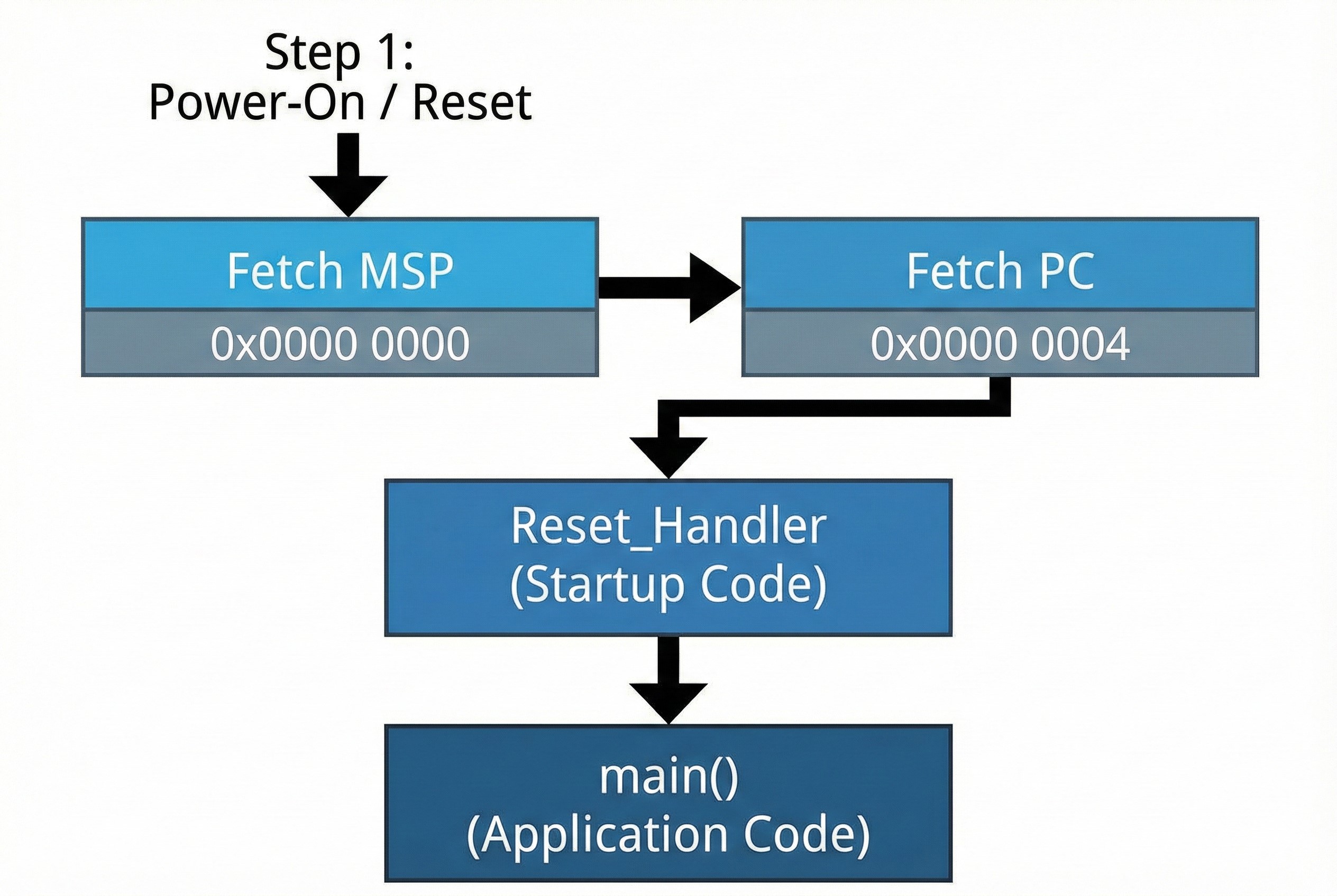
With the memory mapping established, the Cortex-M processor core takes two crucial, non-negotiable steps:
- Fetch the Main Stack Pointer (MSP): The processor reads the 32-bit value located at address
0x00000000. It loads this value into the Main Stack Pointer register (MSP). As we learned previously, the stack is essential for function calls and local variables, so establishing its location is the very first priority. - Fetch the Program Counter (PC): The processor reads the 32-bit value at the next address,
0x00000004. It loads this value into the Program Counter (PC). The PC always holds the address of the next instruction to be executed. This value is the starting address of our program's startup code.
This initial, two-step hardware sequence is elegantly simple and is the foundation of the entire boot process.
The Vector Table: A Table of Starting Points
So, what exactly is at addresses 0x00000000 and 0x00000004? These are the first two entries of the vector table. The vector table is essentially an array of pointers (addresses) located at the very beginning of your program in Flash memory. Its primary role is to tell the processor where to find the handler routines for various system events, such as interrupts and faults.
The first entry is the initial value for the stack pointer, and the second entry is the address of the Reset_Handler function—the very first piece of your code that the processor will execute.
The blog post "Going Bare Metal on STM32" provides a concise explanation of this boot sequence and the vector table's role.
This article clearly describes the boot sequence, memory aliasing, and the function of the vector table.
Read the section "Boot Sequence" for a textual summary of the process we've just discussed. Then, read the short section "Vector Table" to solidify your understanding of its structure.

You might notice something interesting about the reset vector's address. The actual address of a function in ARM assembly is always even. However, the value stored in the vector table for that function will have its least significant bit (LSB) set to 1. This is a special signal to the processor that the code at that address is in Thumb mode, the high-density instruction set used by all Cortex-M processors. The hardware automatically ignores the LSB when loading the address into the PC.
The Reset Handler: Preparing the C Environment
Once the hardware has loaded the PC, it jumps to the Reset_Handler. We have now transitioned from the hardwired boot sequence to executing software from our own program. This startup code, often found in a file named startup_stm32xxxx.s, is typically written in assembly language because it performs low-level tasks before the C runtime environment is ready.
The primary responsibility of the Reset_Handler is to prepare memory so that your C code can run as expected. This involves two critical tasks that directly relate to the memory layout concepts from our previous lesson:
-
Initialize the
.datasection: Global and static variables that you initialize with a non-zero value (e.g.,int counter = 100;) have their initial values stored in Flash. However, for the program to modify them, they must reside in SRAM. The startup code meticulously copies these initial values from their Load Memory Address (LMA) in Flash to their Virtual Memory Address (VMA) in SRAM. -
Initialize the
.bsssection: Global and static variables that are uninitialized or initialized to zero (e.g.,static char buffer[1024];) don't need their initial values stored in Flash—that would be a waste of space. The linker simply reserves space for them in SRAM. The startup code iterates through this.bssregion and writes zeros to every byte, fulfilling the C standard's requirement.
The article "“Bare Metal” STM32 Programming (Part 2): Making it to 'Main'" provides an excellent, commented assembly implementation of this logic.
“Bare Metal” STM32 Programming (Part 2): Making it to 'Main'
This article provides a bare-metal look at the startup code, showing the assembly instructions that perform the crucial memory initialization.
Focus on the section "‘Boot’ Logic". This shows and explains the assembly code for setting the stack pointer, copying the .data section, and zeroing the .bss section. Given your background, seeing the actual load and store instructions (LDR, STR) that perform these memory operations will connect the high-level concept to the low-level implementation.
After these memory initialization routines are complete, the Reset_Handler may perform other system initializations, such as configuring the system clock. Finally, it makes its last and most important call: a branch to your main() function.
The video "How a Microcontroller starts" walks through this entire process, from examining the default ST-provided startup file to building a custom one from scratch. Watching this will help visualize the concepts we've covered.
This video provides a detailed, practical walkthrough of the entire startup process, bridging the gap between theory and code.
First, watch the segment on hardwired startup, which reinforces the role of the vector table in loading the PC and SP registers. Next, watch the explanation of C runtime initialization. This shows how ST's default startup code handles the .data and .bss sections and then calls main. Finally, see these concepts implemented from scratch. The segment from implementing initialization shows the author writing the C code to copy the .data and zero the .bss sections, demonstrating precisely the logic we've been discussing.
Conclusion
The boot sequence is a beautifully orchestrated handoff from hardware to software. It begins with the processor's rigid, predictable hardware actions and concludes with the flexible, preparatory tasks of the software startup code.
Let's summarize the complete journey:
- Power-On/Reset: The
BOOT0andBOOT1pins are sampled to determine the boot memory. - Memory Remapping: The selected boot memory (typically Flash) is aliased to address
0x00000000. - Hardware Fetch: The CPU core automatically loads the Main Stack Pointer from
0x00000000and the Program Counter (with theReset_Handleraddress) from0x00000004. - Execute Startup Code: The CPU jumps to the
Reset_Handler. - Initialize RAM: The
Reset_Handlercopies the.datasection from Flash to SRAM and clears the.bsssection in SRAM to zero. - Call
main(): The startup code branches to themain()function, and your application begins.
We've now seen how the first two entries of the vector table are crucial for starting the processor. In our next lesson, we will explore the rest of the vector table and its vital role in handling asynchronous events like interrupts and system faults, which is key to writing responsive and robust embedded applications.