Introduction
In our last lesson, we traced the boot sequence from power-on to the first line of main(), discovering that the first two entries in the vector table are fundamental to this process. We saw how the processor uses them to find the initial stack pointer and the Reset_Handler function. Now, we'll zoom out and examine the vector table in its entirety. This lesson will show you that the vector table is not just for starting up; it's the central nervous system for handling all asynchronous events in a microcontroller.
Our goal is to explain the full structure of the vector table and its critical role in what is broadly known as exception handling. You'll learn how events ranging from critical system faults to simple button presses are efficiently managed by the processor, using the vector table as its guide. This concept is a cornerstone of writing responsive and robust embedded software.
What are Exceptions and Interrupts?
Before we dive into the table itself, let's clarify our terms. In the ARM Cortex-M architecture, an exception is any condition that causes the processor to deviate from its normal flow of execution. This is a broad category that includes everything from the initial reset to hardware faults and external signals.
An interrupt is a specific type of exception, usually one triggered by a peripheral outside the CPU core (like a timer or a GPIO pin). Therefore, all interrupts are exceptions, but not all exceptions are interrupts.
Every exception is identified by two key attributes: an Exception Number and a Priority Level. For our discussion today, the Exception Number is paramount. It is a unique integer that the hardware uses as an index to find the correct response routine.
The following article from the Memfault blog provides a precise definition of these concepts.
A Practical guide to ARM Cortex-M Exception Handling
This article introduces the core concepts of the ARM exception model.
Please read the introductory section, ARM Exception Model Overview. Pay close attention to the definitions of "Exception Number" and "Priority Level," as the Exception Number is the key that unlocks the vector table.
The Vector Table: A Dispatch Directory
At its core, the vector table is a simple but powerful data structure: an array of 32-bit memory addresses. Each entry in the table is a pointer to a function, which we call an Exception Handler or, for peripheral-generated events, an Interrupt Service Routine (ISR). The position of each pointer in the array is determined by its corresponding Exception Number.
When an exception occurs, the processor hardware automatically performs a lookup in this table. It uses the exception number to calculate the memory offset, fetches the address stored at that location, and jumps to that address, beginning execution of the handler.

This mechanism is extremely efficient because it's handled directly by the hardware, ensuring a fast and predictable response to system events. The following video explains this lookup mechanism clearly.
This video from the "Embedded Systems and Deep Learning" channel visually explains the vector table's structure and its contents.
Watch the segment from the explanation of the interrupt vector table. It describes the table as an array of function pointers and shows how the processor uses the interrupt number to find the correct ISR. Then, continue through the example table for an STM32L4, which gives a concrete view of its contents.
Anatomy of the Vector Table
As we saw in the previous lesson, the vector table must be located at the very beginning of the address space the processor boots from. Its layout is standardized by ARM. The first entry (at offset 0) is the initial stack pointer value. The subsequent entries are the pointers to the exception handlers, starting with Exception Number 1.
The table can be conceptually divided into two parts:
- System Exceptions (Core-level): These are exceptions defined by the ARM Cortex-M architecture itself and are present on any microcontroller using this core.
- External Interrupts (Peripheral-level): These are defined by the microcontroller vendor (e.g., STMicroelectronics) and are connected to the chip's specific peripherals.
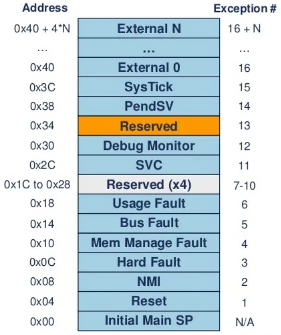
1. System Exceptions (Numbers 1-15)
These handlers manage events generated by the processor core itself. They are critical for the chip's basic operation and for handling errors.
- Exception 1: Reset: As we know, this is the
Reset_Handler, the entry point for our code after a reset. - Exception 2: NMI (Non-Maskable Interrupt): An interrupt that cannot be disabled by software. It's reserved for the most critical events, like detecting a failure in the clock system.
- Exception 3: HardFault: This is the universal "catch-all" fault handler. It's triggered by various error conditions, such as trying to access an invalid memory address or dividing by zero. A robust
HardFault_Handleris an essential tool for debugging. - Exceptions 4-6 (MemManage, BusFault, UsageFault): On more advanced Cortex-M cores (like M4/M7), the HardFault can be broken down into more specific fault types, allowing for more granular error analysis.
- Exception 11: SVCall (Supervisor Call): An exception triggered deliberately by the
SVCinstruction. This is the primary mechanism used by Real-Time Operating Systems (RTOS) to transition from user-level code to privileged kernel code to request system services. - Exception 14: PendSV (Pendable Service Call): A low-priority interrupt that can be triggered by software. It's widely used by RTOS schedulers to perform context switching between tasks.
- Exception 15: SysTick: An interrupt generated by a simple, built-in 24-bit countdown timer. This is the heartbeat of many embedded systems, often used to provide a regular time base for an RTOS or other periodic tasks. We will explore this in a later lesson.
2. External Interrupts (Numbers 16 and up)
These exceptions are triggered by peripherals outside the processor core. They are managed by a component called the Nested Vectored Interrupt Controller (NVIC), which we will explore in detail in the next module. The vector table provides the addresses, and the NVIC manages the priorities and enabling/disabling of these interrupts.
Examples include:
- A
TIM2_IRQHandlerfor a Timer 2 event. - A
USART1_IRQHandlerfor data being received on the UART1 peripheral. - An
EXTI0_IRQHandlerfor a signal change on a GPIO pin (e.g., a button press).
The Memfault article provides a good summary of this division.
A Practical guide to ARM Cortex-M Exception Handling
This reading distinguishes between the core's built-in exceptions and the peripheral-driven external interrupts. It also shows a practical example of a vector table.
First, read the section "Built in Exceptions". Then, read the following section on "External Interrupts". Finally, to see how this looks in a real project, scroll down to the "Setup Prep" subsection and examine the assembly code that begins with the vector table definition.
The Exception Handling Process
When an exception occurs, the processor performs a sequence of actions in hardware, ensuring a rapid and deterministic response. This process avoids the overhead and variability of a purely software-based solution.
- The processor finishes its current instruction.
- The processor automatically saves the current context by pushing a set of key registers (including the Program Counter, Program Status Register, and Link Register) onto the stack. This is called stacking.
- While stacking occurs, the processor fetches the corresponding handler's address from the vector table.
- The processor loads this address into the Program Counter and begins executing the handler code.
- When the handler finishes, it executes a special return instruction. This signals the processor to unstack—restoring the saved registers from the stack.
- Execution resumes at the exact point where the original program was interrupted.
This hardware-automated context switching is a key feature of the Cortex-M architecture, making it highly suitable for real-time applications.
This guide explains the hardware-driven process of entering and exiting an exception handler.
In Chapter 2, find section 2.4.5.1, "NVIC Operation Exception Entry And Exit". Read the paragraph that starts here. This details the efficient, microcoded stacking/unstacking process. Then, briefly read the three short paragraphs under "NVIC Configuration And Use" to see how the vector table fits into the overall setup process.
The Vector Table in Code
In a typical STM32 project, the vector table is defined in the assembly startup file (e.g., startup_stm32f407xx.s). It's usually declared as an array of pointers with weak linkage for each handler. This allows you to override the default, empty while(1) handler by simply defining a function with the same name (e.g., void SysTick_Handler(void)) anywhere in your C code.
While assembly is traditional, it's also possible to define the vector table directly in C, as you might have seen in the video from our last lesson. This approach makes the structure very clear, as it's just an array of function pointers.
This video from Artful Bytes, which we used in the last lesson, demonstrates creating a vector table in C and verifying its contents.
Watch the segment from defining the interrupt vector table in C. This shows how it's constructed as an array of function pointers. Then, watch the verification step from looking at the disassembly, where the debugger confirms that the addresses for the stack, reset handler, and hardfault handler have been correctly placed at the start of flash memory.
This final step of ensuring the table is at the right memory location is the job of the linker, which we will discuss in our next lesson.
Conclusion
Today we've seen that the vector table is far more than just a component of the boot sequence. It is the processor's essential directory for responding to any event that requires its immediate attention.
Here are the key takeaways:
- The vector table is an array of memory addresses, where each address points to an exception handler or Interrupt Service Routine (ISR).
- The hardware uses the unique Exception Number of an event as an index into this table to find the correct handler.
- The table contains entries for both core system exceptions (like Reset, HardFault, and SysTick) and vendor-specific external interrupts from peripherals (like timers and GPIO).
- The process of saving context, jumping to the handler, and returning is handled automatically and efficiently by the processor hardware.
We now have a complete picture of what the vector table is and why it's so important. In our next lesson, we will focus on the linker script, the tool that allows us to tell the compiler and linker precisely where to place the vector table and all other parts of our program in the microcontroller's memory.