Hello! Welcome to your first hands-on lesson with Arduino.
In our previous session, we established the theoretical groundwork. You learned that Arduino is a complete ecosystem combining open-source hardware (microcontroller boards) and a software framework. Most importantly, we demystified the "Arduino language," revealing it to be C++ with a set of convenient hardware-specific libraries and a program structure built around the setup() and loop() functions.
Today, we move from theory to practice. Our goal is to write and upload a sketch using the Arduino IDE to control an LED. This is the classic "Hello, World!" of the physical computing world. By the end of this lesson, you'll have set up your development environment, written your first piece of code to control hardware, and seen it work in the real world.
1. Setting Up Your Development Environment
Before we can control anything, we need the right software. This is the Arduino Integrated Development Environment (IDE), which you'll use to write, compile, and upload your code (called "sketches").
While there are several options, including a web editor and more advanced setups like VS Code with PlatformIO, we'll start with the standard Arduino IDE as it's the most straightforward way to get started.
Arduino MASTERCLASS | Full Programming Workshop in 90 Minutes!
This section of the 'Arduino MASTERCLASS' from Programming Electronics Academy provides a complete walkthrough of the setup process. It covers downloading the IDE, installing it, connecting a board, and selecting the correct board and port, which are crucial first steps.
Please watch from 20:27 to 28:50. This will guide you through installing the IDE and uploading the pre-made 'Blink' example, which we will dissect and write ourselves shortly. The video also mentions the web editor and simulator options, which are good to be aware of if you don't have a physical board yet.
To summarize the key steps for connecting your board:
- Install the IDE: Download and install the latest Arduino IDE from the official website.
- Connect your Arduino: Plug it into your computer using a USB cable.
- Select your board: Go to
Tools > Boardand choose the model you are using (e.g., "Arduino Uno"). - Select your port: Go to
Tools > Portand select the serial/COM port that your Arduino is connected to. The IDE usually indicates which one is the Arduino board.
If you don't have a physical Arduino board, you can use the free simulator at Tinkercad.com, which provides a virtual Arduino Uno and basic electronic components.
2. The Program Structure: setup() and loop()
As we discussed previously, every Arduino sketch has two main functions that you must define. This structure is different from a typical C++ program that starts with main(), but remember, the Arduino toolchain creates the main() function for you behind the scenes.
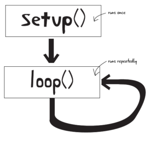
Let's quickly formalize the purpose of these two functions.
[PDF] Programming Arduino: Getting Started with Sketches (Tab)
The book 'Programming Arduino: Getting Started with Sketches' provides a clear, text-based explanation of this structure. It's a great reference to solidify your understanding.
Read the subsections titled 'What Is a Programming Language?' and 'Blink—Again!'. Focus on the explanation of why sketches require the setup() and loop() functions and the role each one plays. The text starts around 'Figure 3.1' and continues to just before the modified code block for the blink sketch.
void setup(): This function is called once when the sketch starts. You'll use it for initialization tasks, like configuring pins or starting a serial communication. It's analogous to a constructor in an object or an initialization block in other programming contexts.void loop(): Aftersetup()completes, this function is called over and over again in a continuous loop for as long as the board has power. This is where the main logic of your program resides, constantly checking inputs and updating outputs. This is similar to the main event loop in a GUI application or a game engine.
3. The Circuit: Connecting an LED
To see our code in action, we need to connect a Light Emitting Diode (LED). You have two options:
Option A: The Onboard LED (Easiest)
Most Arduino boards, including the Uno, have a small surface-mount LED connected directly to one of the digital pins (usually pin 13). A special constant, LED_BUILTIN, is available in the Arduino environment that automatically maps to this pin. This requires no external wiring.
Option B: An External LED (Better Practice)
For real projects, you'll be controlling external components. This is a simple circuit but introduces important concepts like using a breadboard and current-limiting resistors.
Arduino LED - Complete Tutorial
This tutorial from Robotics Back-End explains how to build the circuit and, crucially, why the resistor is necessary. Understanding this is a key part of working with electronics.
Read the section 'Create the Arduino LED circuit'. Pay close attention to the explanation of the LED's polarity (long vs. short leg) and the reason for using a 220 Ohm resistor.
The video below provides a quick visual guide to assembling this circuit.
This short video from Curio Res visually demonstrates the wiring process on a breadboard.
Watch the first 1 minute and 24 seconds to see how the LED, resistor, and wires are connected between the Arduino and the breadboard.
4. The Code: Your First Sketch
Now, let's write the code to make the LED blink. This requires three key Arduino functions:
pinMode(pin, mode): Configures a specific pin to behave as either anINPUTor anOUTPUT. Since we want to send power to the LED, we'll set its pin as anOUTPUT. This is typically done once insetup().digitalWrite(pin, value): Writes a digital value to a pin. The value can beHIGH(which provides 5V, turning the LED on) orLOW(which provides 0V, turning it off).delay(ms): Pauses the program for a specified number of milliseconds. This is essential for controlling the timing of the blink.
The following code implements the blink logic.
// Define the pin connected to the LED.
// Using LED_BUILTIN is the easiest way to start, as it requires no wiring.
// If you wired an external LED to pin 12, you would change this to: #define LED_PIN 12


#define LED_PIN LED_BUILTIN

// The setup function runs once when you press reset or power the board
void setup() {
  // Initialize the digital pin as an output.
  pinMode(LED_PIN, OUTPUT);
}

// The loop function runs over and over again forever
void loop() {
  digitalWrite(LED_PIN, HIGH);   // Turn the LED on (HIGH is the voltage level)
  delay(1000);                   // Wait for a second (1000 milliseconds)
  digitalWrite(LED_PIN, LOW);    // Turn the LED off by making the voltage LOW
  delay(1000);                   // Wait for a second
}
To run this code:
- Open your Arduino IDE. It should start with a blank sketch containing empty
setup()andloop()functions. - Copy and paste the code above into the editor.
- Click the Verify button (the checkmark icon). This compiles your code and checks for errors. You should see a "Done compiling" message.
- Click the Upload button (the right-arrow icon). The IDE will compile the sketch again and transfer it to your Arduino board. You should see the
TXandRXlights on the board flash rapidly during the upload.
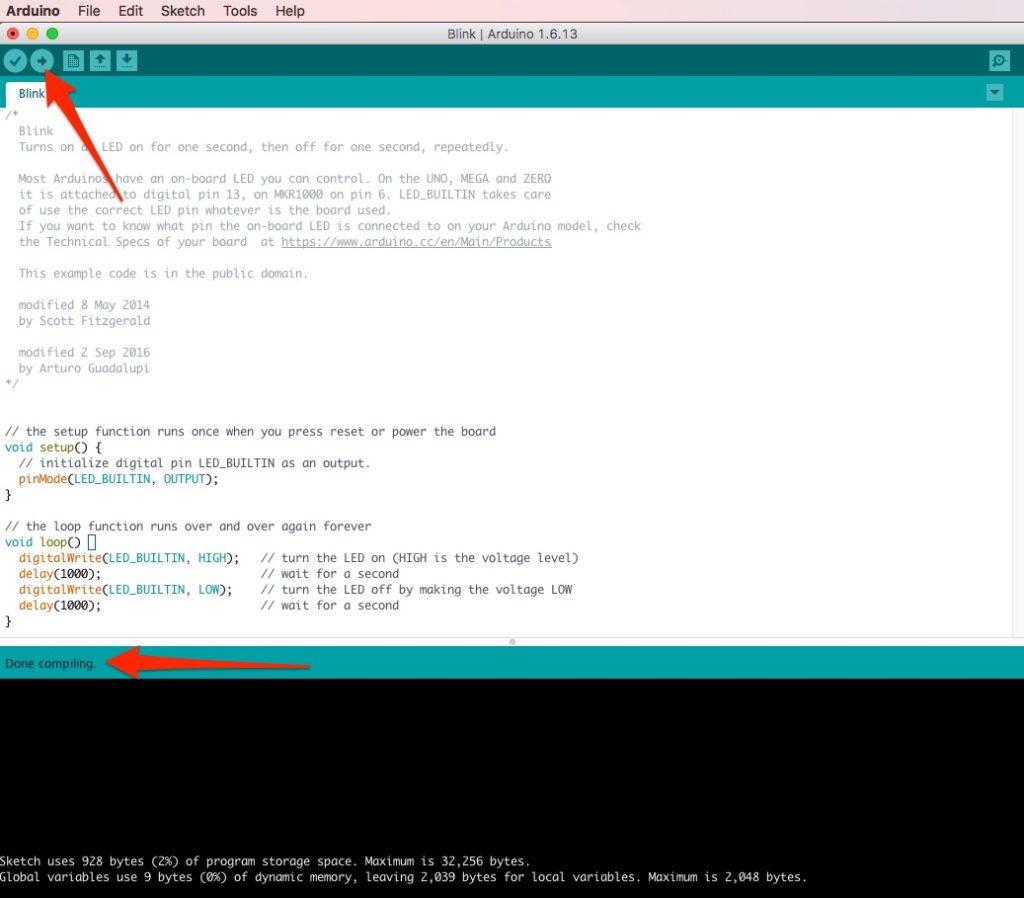
Once the upload is complete, the sketch will start running immediately. You should see the onboard 'L' LED (or your external LED) begin to blink on for one second, then off for one second, repeatedly.
Your Turn: Experiment!
You've successfully run your first sketch. Now, experiment by modifying it. This is the best way to build an intuitive feel for the code.
- How would you make the LED blink twice as fast?
- How would you make it stay on for 2 seconds and off for only 200 milliseconds?
Modify the values inside the delay() functions, upload the code again, and observe the change.
Conclusion
Congratulations! You have bridged the gap between software and the physical world. While simple, this "Blink" sketch is a major milestone.
Key Takeaways:
- You can set up the Arduino IDE by selecting the correct board and port.
- The
setup()function is for one-time initializations, like setting a pin's mode withpinMode(). - The
loop()function contains the main, repetitive logic of the program. digitalWrite()is used to control an output, setting it toHIGH(on) orLOW(off).delay()is a simple way to control the timing of events in your sketch.
Next Up
You've now successfully controlled a digital output. The logical next step is to read a digital input. In our next lesson, we will learn how to read the state of a push button, allowing your Arduino to react to direct physical interaction.