Hello! Welcome back to our exploration of the Arduino.
In the last lesson, we focused on digital inputs, which can only be in one of two states: HIGH or LOW. You learned how to read a push button and, crucially, how to handle the "noisy" signal from a physical switch using a non-blocking debouncing technique with millis().
Today, we move from the binary world of digital signals to the continuous world of analog signals. Many sensors in automation and robotics don't just say "on" or "off"; they provide a range of values, like a temperature sensor reporting how hot it is, or a light sensor reporting how bright it is. This lesson will teach you how to read these analog values from a sensor, using a potentiometer as our example, with the analogRead() function.
This is a fundamental skill for nearly any embedded systems project, allowing your creations to sense and respond to the nuances of the physical world.
1. Analog vs. Digital Signals
Let's start with a quick recap. A digital signal is discrete, like a light switch—it's either fully ON (HIGH) or fully OFF (LOW). This is what we worked with in the last two lessons.
An analog signal, on the other hand, is continuous. It can have any value within a given range. Think of a classic volume knob on a stereo or a dimmer switch for a light. You can turn it to any position, not just on or off.
A potentiometer is a perfect component to demonstrate this. It's a variable resistor that, when wired correctly, acts as a voltage divider to produce a continuously variable voltage.
Arduino Tutorial 12: Understanding Potentiometers
To understand the 'under the hood' theory of how a potentiometer works, this video from Paul McWhorter provides an excellent explanation. It aligns with your interest in knowing how things work at a deeper level.
Watch from 01:03 to 12:41. The first part introduces the component, and the second, more important part explains the internal circuit. Focus on how it functions as a voltage divider with two internal resistors (R1 and R2) and how turning the knob changes the output voltage (Vout).
As you saw, by turning the knob, you change the ratio of resistance, which in turn changes the voltage on the middle pin from 0V all the way up to 5V. But how does the Arduino, a digital device, make sense of this analog voltage?
2. The Analog-to-Digital Converter (ADC)
The Arduino's microcontroller can't work with analog voltages directly. It needs to convert them into a digital number it can understand. This crucial job is performed by a built-in piece of hardware called the Analog-to-Digital Converter (ADC).
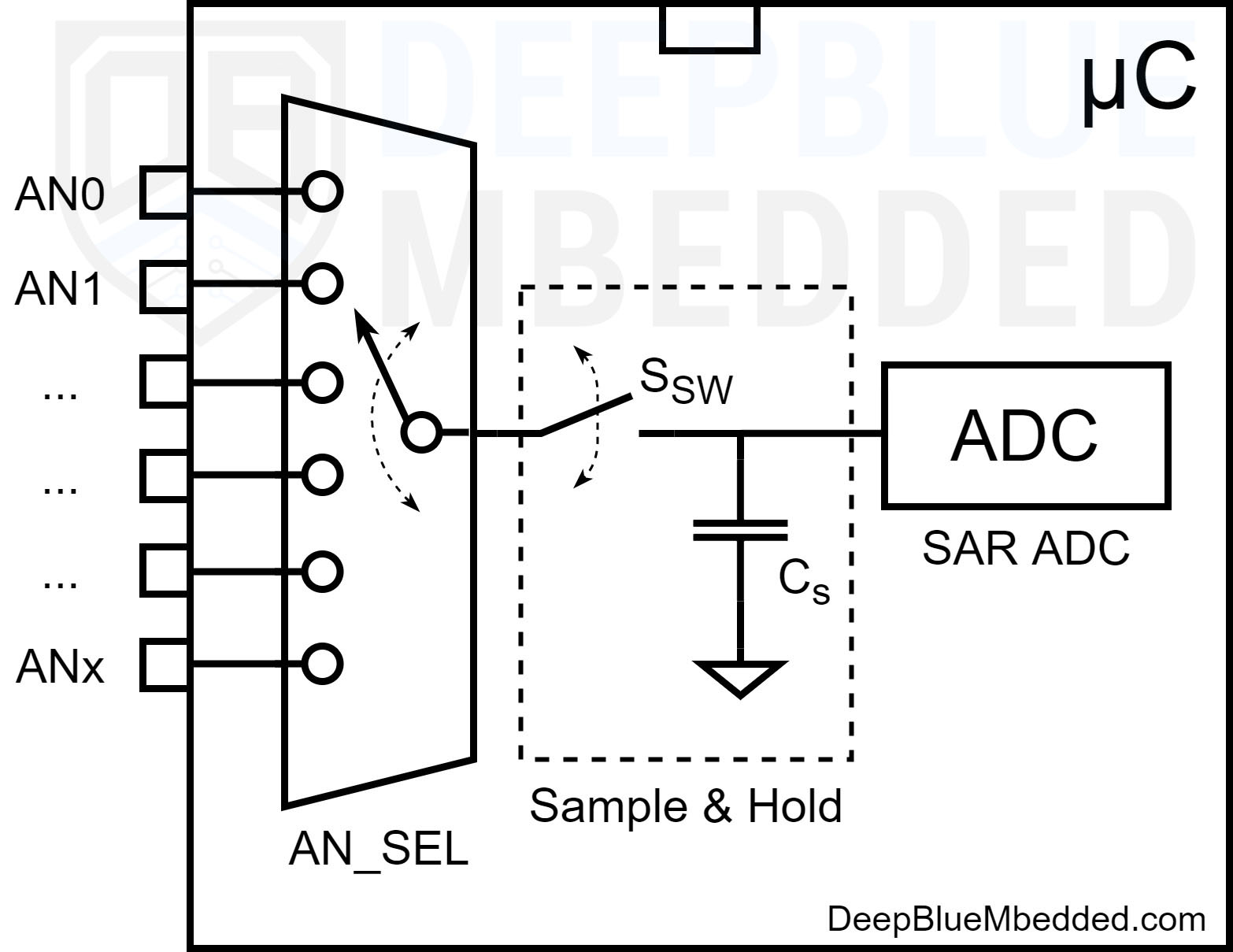
The ADC in the Arduino UNO has two key characteristics:
- Reference Voltage (VREF): By default, this is the board's operating voltage, which is 5V. This is the maximum voltage the ADC can measure.
- Resolution: The ADC has a 10-bit resolution. This means it can represent the analog voltage using discrete steps.
These steps are numbered from 0 to 1023. So, the ADC maps the analog voltage range of 0V to 5V onto the digital number range of 0 to 1023.
- An input of 0V will be converted to the number 0.
- An input of 5V will be converted to the number 1023.
- An input of 2.5V (halfway) will be converted to approximately 512.
This conversion allows your C++ code to work with a simple integer value that represents the real-world voltage.
3. Building the Circuit and Reading the Value
Let's build the circuit and write the code to read a value from the potentiometer.
Wiring
You'll need your Arduino, a breadboard, a potentiometer, and some jumper wires.
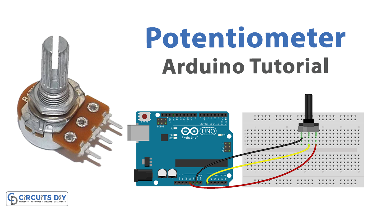
It doesn't matter which outer pin goes to 5V and which to GND; swapping them will simply reverse the direction of the knob's readings (e.g., clockwise increasing vs. counter-clockwise increasing).
The analogRead() Function
Reading the value is surprisingly simple. We use the analogRead(pin) function. It takes one argument—the analog pin you want to read (e.g., A0)—and returns an integer (int) between 0 and 1023.
Let's write a sketch to read the value from pin A0 and display it using the Serial Monitor.
// Define the analog pin we connected the potentiometer to
const int potPin = A0;

void setup() {
  // Initialize the serial monitor to display the readings
  Serial.begin(9600);
}

void loop() {
  // Read the raw value from the potentiometer (0-1023)
  int sensorValue = analogRead(potPin);

  // Print the value to the Serial Monitor
  Serial.print("Raw ADC Value: ");
  Serial.println(sensorValue);

  // Wait a little bit before the next reading
  delay(100);
}
Upload this code, open your Serial Monitor (Tools > Serial Monitor), and turn the potentiometer knob. You should see the numbers change smoothly between 0 and 1023.
4. Converting Raw Values to Voltage
The raw 0-1023 value is useful, but often we want to know the actual voltage being measured. To do this, we need to perform a simple calculation. Since 1023 represents 5V, we can convert our ADC value back to voltage with this formula:
Notice the .0 in 5.0 and 1023.0. This is very important in C/C++. It tells the compiler to perform floating-point arithmetic. If you wrote (5 / 1023), the compiler would perform integer division, which would result in 0, and your voltage calculation would always be zero! Since you're proficient in other languages, you'll recognize this as a key low-level detail to be mindful of in C/C++.
Let's update our code to display the voltage.
const int potPin = A0;

void setup() {
  Serial.begin(9600);
}

void loop() {
  // Read the raw value from the potentiometer (0-1023)
  int sensorValue = analogRead(potPin);

  // Convert the ADC value to a voltage (0V - 5V)
  // Use a float variable to store the result
  float voltage = sensorValue * (5.0 / 1023.0);

  // Print both values
  Serial.print("Raw ADC Value: ");
  Serial.print(sensorValue);
  Serial.print("\t | Voltage: "); // Use a tab character for nice formatting
  Serial.print(voltage);
  Serial.println(" V");

  delay(100);
}
Upload this new sketch. Now your Serial Monitor will show both the raw ADC value and the corresponding voltage, giving you a much more intuitive understanding of the signal.
Arduino Tutorial 12: Understanding Potentiometers
The following sections from Paul McWhorter's video demonstrate the entire process we just discussed: wiring the circuit, writing the code, and seeing the results.
Watch from 12:41 to 26:44. This covers: The physical connection of the potentiometer (12:41). Writing the Arduino code, including the crucial floating-point conversion for voltage (17:12). A final demonstration of the working system with the serial monitor (22:29).
Conclusion
Congratulations! You've successfully bridged the gap between the analog physical world and the digital domain of the microcontroller. You can now read continuous sensor data, a skill that opens the door to countless projects, from building weather stations to creating musical instruments or controlling robotic arms.
Key Takeaways:
- Analog signals are continuous, unlike binary digital signals.
- A potentiometer acts as a variable voltage divider to produce an analog voltage.
- The Analog-to-Digital Converter (ADC) is the hardware that converts an analog voltage into a digital number.
- The Arduino UNO has a 10-bit ADC, which means it maps the 0-5V input range to a digital value from 0 to 1023.
- The
analogRead(pin)function performs this conversion and returns the integer value. - You can convert the raw ADC value back to voltage using the formula
voltage = value * (5.0 / 1023.0), being careful to use floating-point math.
Next Up
Reading an analog value is only half the story. The next logical step is to use that value to control something. In our next lesson, we will learn about Pulse Width Modulation (PWM), a technique that allows an Arduino to produce a pseudo-analog output. We'll combine today's lesson with the next one to use the potentiometer to control the brightness of an LED.