Hello! Welcome back to our Arduino series.
In our last lesson, you learned how to read a continuous analog signal from the physical world using a potentiometer and the analogRead() function. This gave your Arduino the ability to "sense" a range of values, not just a simple ON or OFF.
Today, we'll tackle the other side of the coin: producing a pseudo-analog output. While Arduino's digital pins can only be HIGH (5V) or LOW (0V), we often need to control things with more nuance—like dimming an LED or changing the speed of a motor. This lesson will teach you how to achieve this by controlling an output's brightness or speed using Pulse Width Modulation (PWM) with the analogWrite() function.
This is a cornerstone technique in embedded systems, forming the basis for controlling everything from robotic actuators to lighting systems.
1. The Challenge: Creating "In-Between" Voltages
How can a device that only outputs 0V or 5V create the effect of 2.5V? It can't, at least not directly. Instead, it uses a clever trick called Pulse Width Modulation (PWM).
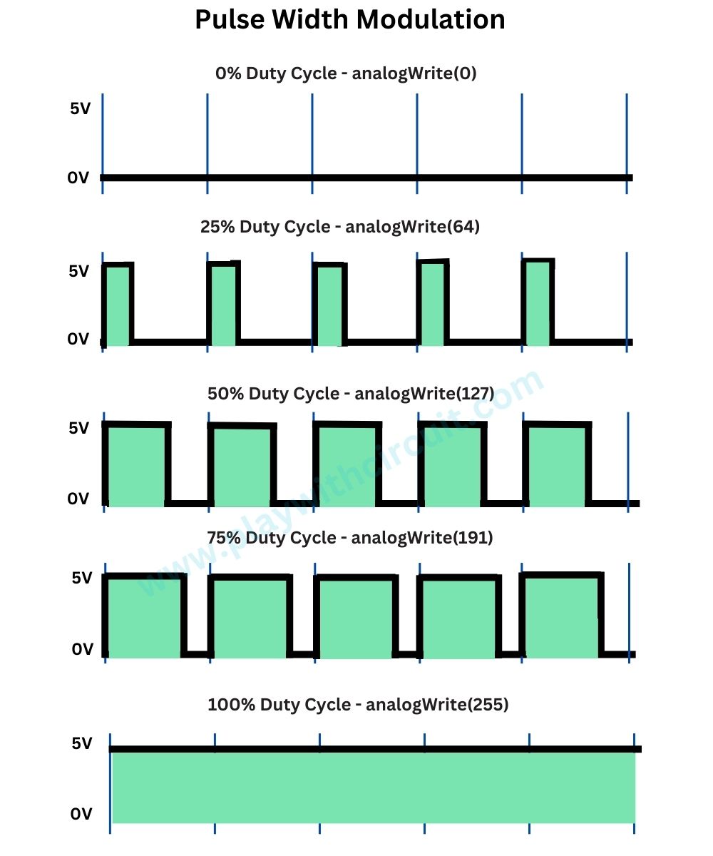
The core idea of PWM is to switch a digital pin on and off very, very quickly. By varying the relative amount of "on-time" versus "off-time", we can change the average voltage delivered to a component. To the component (and our eyes, in the case of an LED), this rapid switching is smoothed out, creating the illusion of a continuous analog signal.
The key concept here is the duty cycle: the percentage of time the signal is HIGH (on) within one complete cycle.
- 0% duty cycle: The signal is always OFF (0V average).
- 50% duty cycle: The signal is ON for half the time and OFF for the other half (2.5V average).
- 100% duty cycle: The signal is always ON (5V average).
The image below perfectly illustrates this concept.
2. The analogWrite() Function
In Arduino, you don't have to manage this rapid switching yourself. The analogWrite() function handles it all for you.
Its syntax is: analogWrite(pin, value);
pin: The pin you want to send the PWM signal to. Important: Not all pins support PWM. On the Arduino Uno, these are pins 3, 5, 6, 9, 10, and 11, typically marked with a tilde symbol (~).value: An integer representing the duty cycle. This is a crucial point: whileanalogRead()had a 10-bit resolution (0-1023),analogWrite()has an 8-bit resolution, so thevalueranges from 0 to 255.analogWrite(pin, 0);corresponds to a 0% duty cycle.analogWrite(pin, 127);is approximately a 50% duty cycle.analogWrite(pin, 255);is a 100% duty cycle.
Arduino analogWrite() Function Tutorial
For a concise and well-structured explanation of PWM and the analogWrite() function, please read the following sections from the DeepBlueMbedded tutorial.
Read the sections 'Arduino PWM Introduction', 'Arduino PWM Pins', and 'Arduino analogWrite() Function'. Focus on the definitions of duty cycle and frequency, which pins you can use for PWM, and the syntax and value range of the analogWrite() function.
3. Under the Hood: Visualizing PWM with an Oscilloscope
You appreciate understanding how things work at a deeper level, so let's look at what's really happening on a PWM pin. The analogWrite() function doesn't create a true analog voltage. It creates a rapidly switching digital signal. The best way to see this is with an oscilloscope.
The following video provides an excellent demonstration. The presenter hooks an oscilloscope up to an Arduino pin and shows you exactly what the signal looks like for different analogWrite() values. This will solidify your understanding of duty cycle.
Arduino Tutorial 8: Understanding Pulse Width Modulation (PWM) and the Arduino Analog Write Command
This video from Paul McWhorter provides an excellent 'under the hood' look at what the PWM signal from analogWrite() actually is.
Watch from the beginning to 16:01. Pay close attention to these key moments: 05:03: See what the oscilloscope shows for analogWrite(0) and analogWrite(255). 09:27: This is the most important part. See what happens with analogWrite(127). Instead of a steady 2.5V, you'll see the signal switching between 0V and 5V. 12:44: Observe how the 'on' time (the pulse width) changes for different values, while the total period of the wave stays the same.
This visualization confirms that PWM is a digital technique to simulate an analog outcome. The "analog" part is the effect it has on devices like LEDs and motors, which respond to the average power they receive over time.
4. Application 1: Fading an LED
The classic "Hello, World!" for PWM is making an LED fade smoothly in and out. This requires a very simple circuit: just an LED and a current-limiting resistor (e.g., 220Ω) connected to a PWM pin.
Circuit:
- Connect Arduino pin 9 to one end of a 220Ω resistor.
- Connect the other end of the resistor to the long leg (anode) of your LED.
- Connect the short leg (cathode) of the LED to a GND pin on the Arduino.
Code:
This code uses two for loops to cycle the brightness value from 0 up to 255 and then back down.
// Use a PWM-capable pin
const int ledPin = 9;

void setup() {
  // Set the pin as an output
  pinMode(ledPin, OUTPUT);
}

void loop() {
  // Fade in from min to max
  for (int brightness = 0; brightness <= 255; brightness++) {
    // Set the LED brightness
    analogWrite(ledPin, brightness);
    // Wait a little bit to see the change
    delay(10);
  }

  // Fade out from max to min
  for (int brightness = 255; brightness >= 0; brightness--) {
    // Set the LED brightness
    analogWrite(ledPin, brightness);
    // Wait a little bit to see the change
    delay(10);
  }
}
Upload this sketch to your Arduino. You should see the LED smoothly fade in and out, demonstrating the power of analogWrite().
5. Application 2: Controlling Motor Speed
The same principle used to control an LED's brightness can be used to control the speed of a DC motor. The motor's speed is proportional to the average voltage it receives.
A Critical Warning: Never connect a DC motor directly to an Arduino's I/O pins. Motors can draw far more current than an Arduino pin can safely supply, which can permanently damage your board. Always use a motor driver circuit, such as an H-Bridge (like the L298N module) or a transistor, to act as a switch that handles the high-current load.

The motor driver will typically have an "Enable" pin. By sending our PWM signal to this pin, we can control the motor's speed. A value of 0 will stop the motor, 255 will run it at full speed, and values in between will adjust the speed accordingly.
Arduino DC Motor Control Tutorial - L298N | H-Bridge | PWM | Robot Car
To see how this is applied in a more realistic robotics context, watch these clips from a tutorial on using the popular L298N motor driver.
Watch the following short segments: 00:33 - 01:33: An introduction to using PWM for motor speed control. 03:55 - 04:28: This explains how the 'Enable' pin on the L298N driver is used for speed control via a PWM signal. 05:31 - 06:11: This shows the code where a potentiometer's value is read, mapped, and then used with analogWrite() to control the motor's speed.
This video nicely demonstrates how the concepts from our last lesson (analogRead) and this lesson (analogWrite) come together to create a complete control system.
Conclusion
You have now mastered one of the most versatile tools in the Arduino ecosystem. By understanding Pulse Width Modulation and the analogWrite() function, you can add nuance and fine control to your projects.
Key Takeaways:
- Pulse Width Modulation (PWM) is a digital technique for simulating an analog output by rapidly switching a pin ON and OFF.
- The duty cycle is the percentage of "on-time" in a cycle and determines the average output voltage.
- The
analogWrite(pin, value)function generates a PWM signal on specific pins (marked with~). - The
valueforanalogWriteis an 8-bit number ranging from 0 to 255. - PWM can be used to control the brightness of LEDs, the speed of motors, and many other outputs that require variable power.
Next Up
So far, we've learned how to get data into the Arduino (analogRead, digitalRead) and how to control outputs (analogWrite, digitalWrite). In the next lesson, we'll focus on the primary method of communication between the Arduino and a host computer: the Serial library. This is essential for debugging your code, sending data to your computer for analysis, and receiving commands to control your Arduino project.