Hello! Welcome to your next lesson in the Data Center Operations and Deployment module.
In our last lesson, you performed a complete, end-to-end server deployment. You took an empty rack space and turned it into a fully functional server with an operating system, accessible for remote management. That single server is now a building block. But what happens if a component in that server, or the infrastructure supporting it, fails? This question is at the heart of data center reliability.
Today, we will focus on exactly that. We'll learn how to look at an entire system, not just one server, and spot the weak links. The learning outcome for this lesson is to analyze an infrastructure diagram to identify single points of failure at the power, network, and storage layers. Understanding this is a non-negotiable skill for any data center professional, as it's the foundation for building resilient and highly available systems.
Redundancy vs. Resiliency: The Core Concepts
Before we start hunting for weak links, we need to clarify two fundamental terms: redundancy and resiliency. They are often used interchangeably, but they have distinct meanings.
- Redundancy is the practice of duplicating critical components or functions of a system (e.g., having two power supplies). It's a method.
- Resiliency is the ability of a system to withstand and recover from failures, ensuring continued operation. It's the ultimate goal.
You use redundancy to achieve resiliency. Let's watch a short video that introduces this concept using some clever analogies before diving into technical examples.
Resiliency vs. Redundancy in the Data Center - 1177
The video 'Resiliency vs. Redundancy in the Data Center' from My PlayHouse does a great job of explaining the core idea in a very approachable way.
Watch the first two minutes of the video (00:00 - 02:08). Pay attention to the distinction made between having duplicate components (redundancy) and the system's ability to survive a failure (resiliency).
What is a Single Point of Failure (SPOF)?
A Single Point of Failure (SPOF) is any part of a system that, if it fails, will stop the entire system from working. Our job is to find and eliminate SPOFs by strategically adding redundancy. We'll now look at the three critical layers of infrastructure—power, network, and storage—and learn how to spot these weak links.
Analyzing the Power Layer for SPOFs
Power is the lifeblood of a data center. A power failure is the most common cause of major outages. Let's build a resilient power path from the utility pole all the way to the server's processor.
The video we just started is perfect for this. It builds a power infrastructure from the ground up, identifying the SPOF at each stage.
Resiliency vs. Redundancy in the Data Center - 1177
Let's continue with the 'Resiliency vs. Redundancy' video to see how a resilient power chain is constructed.
Watch the section from 02:08 to 10:17. The presenter starts with a single server and systematically eliminates SPOFs. Follow along as he adds: Redundant Power Supply Units (PSUs) in the server. Two separate rack Power Distribution Units (PDUs). Two separate Uninterruptible Power Supplies (UPS). Two separate power feeds/transformers and backup generators. At each step, ask yourself: 'If this new component fails, what happens? What is the next single point of failure?'
The video gives a great practical overview. Now let's look at a more formal diagram of a fully redundant power chain.
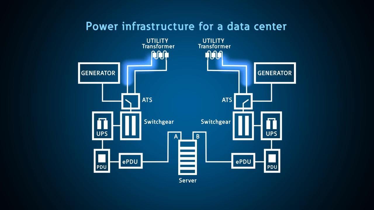
This "A/B" power design is the industry standard. It ensures that the failure of any single component in one path does not take the server offline, because the other path remains active.
However, even in designs that look redundant, hidden SPOFs can exist. This is the kind of deep knowledge that will set you apart in a job interview.
Avoiding Single Point of Failure Design Flaws
The article 'Avoiding Single Point of Failure Design Flaws' by SM&W discusses real-world examples where expensive, redundant designs still contained critical SPOFs. This is an excellent resource for understanding the 'why'.
Read the following sections to see how complex power systems can fail: Start with the introduction to understand the premise: redundancy does not automatically eliminate failure. Read the section 'False generator redundancy'. It explains how the way generators are connected can create a SPOF, even if you have a spare one. Read 'Automatic transfer switch bottlenecks'. This shows how the ATS—the device that switches between utility and generator power—can itself be a SPOF if it can't be bypassed for maintenance.
Analyzing the Network Layer for SPOFs
Just like with power, our goal is to ensure there is no single cable, port, or device whose failure would disconnect our server from the network.

To achieve this, we use a technique called Multipathing. This simply means creating multiple physical paths for data to travel between the server and the rest of the network.
Resiliency vs. Redundancy in the Data Center - 1177
Let's return to the 'Resiliency vs. Redundancy' video to see how multipathing is applied to a server's network connection.
Watch the segment from 10:17 to 14:50. The presenter builds a resilient network connection by adding: Two separate Network Interface Cards (NICs) in the server. Connections to two separate Top-of-Rack (ToR) switches. Uplinks from the ToR switches to two separate core switches. Two separate internet connections.
The video demonstrates the physical setup. The article below explains the concept of multipathing in more detail, which is fundamental to both networking and storage.
Demystifying Multipathing in Modern Networking
The article 'Demystifying Multipathing in Modern Networking' explains the software and logic behind using multiple network paths for both redundancy and performance.
Read these sections to understand the technical details behind network resiliency: Read the introduction and 'The Mechanics of Multipathing' to get a solid definition of what multipathing is and how path management software works. Skim 'Fault Tolerance and Redundancy in Network Design' to reinforce how this approach eliminates SPOFs.
Analyzing the Storage Layer for SPOFs
In the previous lesson, you configured a RAID array. RAID provides redundancy at the disk level within a single server, protecting against the failure of one or more hard drives. That's the first step.
But what if the entire server fails? The data on it becomes unavailable. To guard against this, data is often moved from local server disks to a dedicated, shared network for storage called a Storage Area Network (SAN). The same principles of redundancy and multipathing apply here.
Resiliency vs. Redundancy in the Data Center - 1177
The 'Resiliency vs. Redundancy' video touches on this transition from local storage to a resilient SAN.
Watch the section from 14:50 to 18:03. Notice the familiar pattern: the server is equipped with two separate host bus adapters (HBAs), which connect to two separate Fibre Channel switches, which in turn connect to a storage array that has its own internal redundancy.
The concept of multipathing is central to how modern servers talk to SANs.
Demystifying Multipathing in Modern Networking
Let's revisit the 'Demystifying Multipathing' article, this time focusing on its role in storage.
Read the following sections: 'Multipathing in Storage Area Networks (SANs)': This section explains exactly why multipathing is so critical in a SAN environment. 'Multipathing in Virtualized Environments': This is a very common use case. It explains how multipathing ensures multiple virtual machines can reliably access shared storage without creating bottlenecks or SPOFs.
Test Your Understanding
Let's apply what you've learned. Imagine you are reviewing a diagram for a new server deployment. You see the following:
- The server has two power supplies.
- Power supply A is plugged into rack PDU 'A1'. Power supply B is also plugged into rack PDU 'A1'.
- Rack PDU 'A1' is connected to UPS 'A'.
- The server has two network cards (NICs).
- NIC 1 is connected to switch 'A'. NIC 2 is connected to switch 'B'.
- The server is using its local disks, configured in a RAID 10 array.
Question: Where are the single points of failure in this design? How would you fix them?
Click to reveal the analysis
-
Power Layer SPOF: Rack PDU 'A1'. Although the server has two power supplies, both are connected to the same PDU. If PDU 'A1' fails or its breaker trips, the server will lose all power.
- Fix: Connect power supply B to a separate PDU (e.g., 'B1') that is on a separate power circuit (ideally connected to UPS 'B').
-
Network Layer: No SPOF is described. The design correctly uses two NICs connected to two separate switches, which is good practice.
-
Storage Layer SPOF: The server itself. While RAID 10 protects against disk failure, the data is still only on this one server. If the server's motherboard fails, or the entire server needs to be taken down for maintenance, the data becomes inaccessible.
- Fix: For higher availability, the data could be moved to a dual-controller SAN, with the server connecting via two HBAs to two separate SAN switches. Alternatively, the application could be clustered across two servers, with data replicated between them.
Conclusion
Today you've learned how to think like a data center architect, scrutinizing designs for weakness. Building and maintaining resilient systems is a core responsibility of data center operations.
Key Takeaways:
- A Single Point of Failure (SPOF) is any component whose failure will cause a wider service outage.
- Resiliency (the goal) is achieved through redundancy (the method).
- Resiliency must be designed into every layer:
- Power: A fully redundant "A/B" path from the utility to the server's dual PSUs.
- Network: Dual NICs, dual switches, and redundant uplinks, using multipathing to manage the connections.
- Storage: Redundancy at the disk level (RAID) and, for higher availability, at the system level (SANs or replication).
- Simply buying two of everything is not enough. You must analyze the entire chain to find hidden SPOFs, such as common circuit breakers or non-bypassable components.
In our next lesson, we will move from identifying potential failures to proactively preventing them. You will learn how to perform preventive maintenance, including firmware updates and hardware health checks, which are essential tasks for ensuring the long-term reliability of the infrastructure you manage.