Hello! Let's dive into the final lesson of our module on timers and interrupts.
In our previous session, we established the "golden rules" for writing efficient Interrupt Service Routines (ISRs), focusing on deferred processing using semaphores to keep ISRs short and fast. Today, we'll apply these exact principles to solve one of the most common problems in embedded systems: handling noisy inputs from mechanical switches.
This lesson directly addresses the learning outcome: Implement a debouncing algorithm for GPIO inputs using a hardware timer. We will see how a timer, combined with a well-designed ISR, provides a robust and non-blocking solution to ensure that a single physical button press is registered as a single digital event.
1. The Problem: Unpredictable Bouncing
From your mechanical engineering background, you know that when two metal contacts collide, they don't make a clean, single connection. They physically bounce off each other several times at a microscopic level before settling. This creates a rapid series of electrical connections and disconnections.
A microcontroller is so fast that it sees this bouncing not as one event, but as dozens of them.
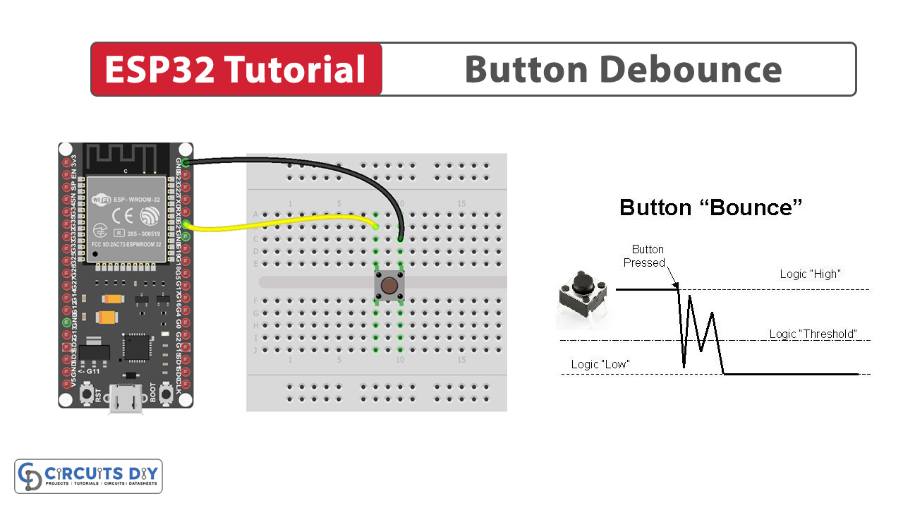
If you were to attach a standard GPIO interrupt to this pin, the ISR would fire multiple times for a single press, leading to erratic and unpredictable behavior in your application.
2. The Solution: Timer-Based Validation
The common strategy to defeat bouncing is to introduce a waiting period. A naive approach might be to detect an initial change and then use vTaskDelay() to wait for the bouncing to stop before acting. However, as we learned in the last lesson, blocking calls like delays are forbidden in ISRs and highly inefficient in main loops.
A much better, non-blocking solution is to use a hardware timer. The core idea is to sample the button's state at a regular interval and only accept a state change if the state remains stable for a minimum period of time (the "debounce delay").
We will set up one of the ESP32's hardware timers to fire an ISR periodically. This ISR's only job will be to run our debouncing logic.

3. Debouncing Algorithms
There are two common algorithms for timer-based debouncing. Both are executed within the periodic timer ISR.
Method 1: The Counter/Integrator Algorithm
This is a straightforward and effective method.
- The timer ISR runs periodically (e.g., every 5ms).
- In the ISR, we read the current state of the GPIO pin.
- We maintain a counter. If the current pin state is 'pressed', we increment the counter. If it's 'released', we reset the counter to zero.
- We only consider the button to be officially 'pressed' when the counter reaches a certain threshold (e.g., 10, which corresponds to 10 * 5ms = 50ms of stable pressed state).
- Once the button is officially 'pressed', we can signal our main application. A similar logic is used to detect a stable 'released' state.
This "integration" of the signal over time effectively filters out the high-frequency noise of the bounce.
Let's look at a practical, though slightly different, implementation of this idea.
ESP32 Capacitive Touch Input Using "Metallic Hole Plugs ...
The article 'ESP32 Capacitive Touch Input...' provides a working example of a timer-based filter, which is functionally a debouncer. While it's for capacitive touch, the software principle is identical for a mechanical button.
Please read 'Step 3: About the Software'. Focus on the description of the InterruptService() routine. Notice how it uses a timer to periodically check the input and a counter (nButtonNCount) that must exceed a threshold (BUTTON_FILTER) before a button is considered 'pressed'. This is a great real-world example of the counter/integrator method.
Method 2: The Shift Register Algorithm
This is another very common and robust technique.
- The timer ISR runs periodically.
- In the ISR, we read the pin's state (as a 0 or 1).
- We maintain a history of the last N reads, typically in an integer used as a bitfield (e.g., a
uint16_tfor the last 16 states). - Each time the ISR runs, we shift the history bits over by one and add the new state.
- A 'press' is detected when the history register matches a specific pattern that indicates a stable state. For example, if 'pressed' is logic low, we might wait for the 16-bit history to become
0x0000. A 'release' would be detected when it becomes0xFFFF.
This method is excellent because it confirms stability by looking at a complete window of recent history.
a 16-bit pattern-based button debouncing library for ESP32 ...
This GitHub repository for a debouncing library explains the shift register method clearly.
Please read the section 'How It Works'. It describes exactly this shift register pattern. Note how it detects a press not just by a stable value, but by a transition from unstable/released to stable/pressed (0b0000000000111111), which is a very robust approach.
4. ESP-IDF Implementation Example
Let's implement the counter/integrator method using the modern ESP-IDF gptimer API and FreeRTOS task notifications, which builds directly on our last lesson.
In this example:
- A hardware timer (
gptimer) will fire an ISR every 5 milliseconds. - The ISR will run the counter-based debounce logic.
- When a stable press or release is detected, the ISR uses
vTaskNotifyGiveFromISRto notify a dedicated processing task. - The processing task waits for this notification using
ulTaskNotifyTakeand prints the final, debounced button state.
This architecture perfectly follows the deferred interrupt processing pattern.
#include <stdio.h>
#include "freertos/FreeRTOS.h"
#include "freertos/task.h"
#include "driver/gpio.h"
#include "driver/gptimer.h"
#include "esp_log.h"

#define BUTTON_GPIO         GPIO_NUM_4
#define DEBOUNCE_TIME_MS    50
#define TIMER_RESOLUTION_HZ 1000000 // 1MHz, 1 tick = 1 microsecond
#define TIMER_ALARM_US      5000      // 5ms alarm period

static const char *TAG = "DEBOUNCE";

// Globals shared between ISR and task
static TaskHandle_t s_button_task_handle = NULL;

// Struct to hold state for one debounced button
typedef struct {
    uint8_t pin;
    bool current_state;
    bool last_debounced_state;
    int press_counter;
    int release_counter;
    int counter_threshold;
} debounce_state_t;

// Initialize the state for our button
static debounce_state_t button_state = {
    .pin = BUTTON_GPIO,
    .current_state = true, // Assume released (high due to pull-up)
    .last_debounced_state = true,
    .press_counter = 0,
    .release_counter = 0,
    // (50ms debounce time) / (5ms timer period) = 10 counts
    .counter_threshold = DEBOUNCE_TIME_MS / (TIMER_ALARM_US / 1000)
};

// Timer ISR - This is our "top half"
static bool IRAM_ATTR timer_on_alarm_cb(gptimer_handle_t timer, const gptimer_alarm_event_data_t *edata, void *user_data)
{
    BaseType_t high_task_woken = pdFALSE;
    debounce_state_t *state = (debounce_state_t*) user_data;

    // 1. Read the raw GPIO state
    state->current_state = gpio_get_level((gpio_num_t)state->pin);

    // 2. Run the counter/integrator logic
    if (state->current_state == state->last_debounced_state) {
        // If state is stable, reset counters
        state->press_counter = 0;
        state->release_counter = 0;
    } else {
        // State has changed from the last debounced state
        if (state->current_state == false) { // Change to 'pressed' (active low)
            state->press_counter++;
            state->release_counter = 0;
        } else { // Change to 'released'
            state->release_counter++;
            state->press_counter = 0;
        }
    }

    // 3. Check if threshold is met
    if (state->press_counter >= state->counter_threshold) {
        state->last_debounced_state = false; // Officially pressed
        state->press_counter = 0;
        // 4. Notify the bottom-half task
        vTaskNotifyGiveFromISR(s_button_task_handle, &high_task_woken);
    } else if (state->release_counter >= state->counter_threshold) {
        state->last_debounced_state = true; // Officially released
        state->release_counter = 0;
        // 4. Notify the bottom-half task
        vTaskNotifyGiveFromISR(s_button_task_handle, &high_task_woken);
    }

    return (high_task_woken == pdTRUE); // Yield if a higher priority task was woken
}

// Task to handle debounced events - This is our "bottom half"
static void button_processing_task(void *arg)
{
    s_button_task_handle = xTaskGetCurrentTaskHandle();

    while(1) {
        // Wait for a notification from the ISR.
        // This task uses zero CPU time while waiting.
        ulTaskNotifyTake(pdTRUE, portMAX_DELAY);

        // Notification received, process the event
        if (button_state.last_debounced_state == false) {
            ESP_LOGI(TAG, "Button PRESSED");
        } else {
            ESP_LOGI(TAG, "Button RELEASED");
        }
    }
}

void app_main(void)
{
    // --- GPIO Configuration ---
    gpio_config_t io_conf = {
        .pin_bit_mask = (1ULL << BUTTON_GPIO),
        .mode = GPIO_MODE_INPUT,
        .pull_up_en = GPIO_PULLUP_ENABLE,
        .intr_type = GPIO_INTR_DISABLE // No GPIO interrupts needed!
    };
    gpio_config(&io_conf);

    // --- Task Creation ---
    xTaskCreate(button_processing_task, "button_task", 2048, NULL, 10, NULL);

    // --- Timer Configuration ---
    ESP_LOGI(TAG, "Creating timer for debouncing...");
    gptimer_handle_t gptimer = NULL;
    gptimer_config_t timer_config = {
        .clk_src = GPTIMER_CLK_SRC_DEFAULT,
        .direction = GPTIMER_COUNT_UP,
        .resolution_hz = TIMER_RESOLUTION_HZ,
    };
    gptimer_new_timer(&timer_config, &gptimer);

    gptimer_alarm_config_t alarm_config = {
        .alarm_count = TIMER_ALARM_US,
        .reload_count = 0,
        .flags.auto_reload_on_alarm = true,
    };
    gptimer_set_alarm_action(gptimer, &alarm_config);

    gptimer_event_callbacks_t cbs = {
        .on_alarm = timer_on_alarm_cb,
    };
    gptimer_register_event_callbacks(gptimer, &cbs, &button_state);

    ESP_LOGI(TAG, "Starting timer...");
    gptimer_enable(gptimer);
    gptimer_start(gptimer);
}
Test your understanding!
In the code example above, the debounce time is set to 50ms. Suppose you build the circuit and find that the button still occasionally produces a double-press. You want to make the debouncing more aggressive to eliminate this, even if it makes the button feel slightly less responsive.
Which single constant would you change, and would you increase or decrease its value? What is the trade-off?
Show answer
You would increase the value of DEBOUNCE_TIME_MS. For example, changing it to 75 would mean the button state has to be stable for 75ms before it's recognized.
The counter_threshold is calculated from this, so it would automatically increase from 10 to 15. This makes the algorithm more immune to longer noise bursts.
The trade-off is increased latency. The system will now take at least 75ms to register a valid button press, which might feel slightly sluggish to a user.
Conclusion
Congratulations on completing the Timers and Interrupts module! You've gone from configuring a basic timer to implementing one of the most essential patterns in embedded firmware development. This timer-based debouncing technique is a hallmark of professional, robust design.
Key Takeaways:
- Mechanical switches are electrically noisy, producing a "bouncing" signal that can fool simple digital inputs.
- Using a hardware timer to periodically sample the pin state is an efficient, non-blocking way to implement debouncing.
- Two common debouncing algorithms are the Counter/Integrator method and the Shift Register method.
- A robust implementation uses the Deferred Interrupt Processing pattern: the timer ISR handles the high-frequency sampling, and a separate FreeRTOS task handles the logic that follows a debounced state change.
- This approach keeps the ISR extremely short and fast, adhering to the best practices we established in the previous lesson.
This skill is fundamental and will be invaluable as we start building more complex systems. In our next module, we'll change gears and explore how the ESP32 communicates with the outside world, starting with the ubiquitous UART serial protocol.