Hello! Welcome to the first lesson in our module on serial communication.
In the previous module, we mastered the ESP32's internal world of timers and interrupts, learning how to manage time-critical events and process them efficiently. Now, we shift our focus outwards, to how the ESP32 communicates with other devices.
This lesson addresses the learning outcome: Configure and use UART for serial communication with external devices or a PC. UART is the most fundamental and common serial protocol you'll encounter. We'll cover the core concepts, the ESP-IDF functions for controlling it, the necessary hardware connections, and finally, how to encapsulate this functionality within a C++ class, aligning with our course goal.
1. What is UART?
UART stands for Universal Asynchronous Receiver/Transmitter. It's a piece of hardware that allows your ESP32 to send and receive data, one bit at a time, over a pair of wires.
- Universal: It's a widely supported standard.
- Asynchronous: This is a key concept. Unlike other protocols we'll see later (like I2C and SPI), there is no shared clock signal between the sender and receiver. Instead, they agree on a communication speed (the baud rate) beforehand. Data is framed with start and stop bits, which allows the receiver to synchronize with each incoming byte.
The ESP32 has three hardware UART controllers, numbered 0, 1, and 2. UART0 is almost always used for programming and the default logging output (what you see in the ESP-IDF monitor), so we typically use UART1 or UART2 for communicating with external devices.
Universal Asynchronous Receiver/Transmitter (UART) - ESP32
For a formal overview, please read the introduction section of the official ESP-IDF documentation for UART. It provides a concise summary of what UART is and the ESP32's capabilities.
Read the 'Introduction' section to familiarize yourself with the basic definition and the fact that the ESP32 has three configurable UART controllers.
2. The ESP-IDF UART Workflow
The ESP-IDF provides a clear, three-step process for configuring a UART port before you can use it. This systematic approach is very similar to how we configured hardware timers in the last module.
- Install the Driver (
uart_driver_install): This function allocates memory for the driver, including the crucial receive (RX) and transmit (TX) ring buffers. These buffers allow the driver to handle data in the background without blocking your main code. - Set Communication Parameters (
uart_param_config): This is where you define the serial protocol's specifics. You bundle parameters like baud rate, data bits, parity, and stop bits into auart_config_tstruct and pass it to this function. A standard configuration is "115200 8N1" (115200 baud, 8 data bits, No parity, 1 stop bit). - Set Communication Pins (
uart_set_pin): This function maps the logical UART signals (TX, RX) to physical GPIO pins on the ESP32. Thanks to the ESP32's "GPIO matrix," almost any pin can be used for UART, which is incredibly flexible.
Once these three steps are done, you can start communicating using uart_write_bytes() and uart_read_bytes().
Universal Asynchronous Receiver/Transmitter (UART) - ESP32
To see the official API structure and code snippets for these configuration steps, please review the 'Functional Overview' in the ESP-IDF documentation.
Skim through the sections from 'Functional Overview' down to 'Set Communication Pins'. You don't need to memorize the functions, but pay attention to the three-step sequence and the purpose of uart_driver_install, uart_param_config, and uart_set_pin.
3. A Practical Walkthrough: Sending and Receiving Data
Now let's see how these steps come together in a real application. The following video provides an excellent step-by-step tutorial for creating a project that both sends and receives data over UART.
ESP32 UART Communication with ESP-IDF #1 | Simple TX & RX Tutorial
This video from ControllersTech provides a clear, practical demonstration of setting up and using UART with the ESP-IDF. We will use it to see the configuration, transmission, and reception processes in action.
Please watch the following segments: Configuration (02:29 - 06:11): Pay close attention to how the uart_config_t struct is populated and how the uart_driver_install, uart_param_config, and uart_set_pin functions are called. This is the practical application of the documentation you just read. Sending Data (06:11 - 07:37): Observe how the tx_task uses uart_write_bytes to send a string. Receiving Data (07:37 - 09:11): Note how the rx_task allocates a buffer and uses uart_read_bytes to receive data. Pay special attention to the timeout parameter; it determines how long the function will wait for data to arrive.
Key Functions for Communication
As you saw in the video, the two main functions for data transfer are:
-
int uart_write_bytes(uart_port_t uart_num, const char* src, size_t size): This function copies data from your provided buffer (src) into the TX ring buffer. The UART driver then sends this data out in the background. It's non-blocking in the sense that it returns once the data is in the buffer, not necessarily when all the data has been physically transmitted. -
int uart_read_bytes(uart_port_t uart_num, void* buf, uint32_t length, TickType_t ticks_to_wait): This function reads data from the RX ring buffer into your application's buffer (buf). Theticks_to_waitparameter is crucial:- If set to 0, it returns immediately with any data that is currently available.
- If set to a value > 0, it will wait for up to that amount of time for the requested number of bytes (
length) to arrive. - If set to
portMAX_DELAY, it will wait indefinitely.
4. Hardware Setup and Pin Selection
Software is only half the story. To communicate with a PC, you need a physical connection. Since your PC uses USB and the ESP32 speaks UART, you need a translator: a USB-to-TTL Serial Converter, often based on a chip like the FTDI FT232 or CP2102.
The wiring is simple but has one critical detail: the connection is crossed.
- ESP32 TX (Transmit) pin connects to the converter's RX (Receive) pin.
- ESP32 RX (Receive) pin connects to the converter's TX (Transmit) pin.
- Connect GND between the ESP32 and the converter.

Choosing Your Pins
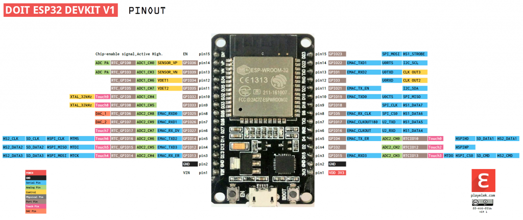
You can use the pinout diagram for your specific board to identify appropriate GPIOs. UART0 is used by the monitor, so for a secondary serial channel, you might choose the default pins for UART2 (GPIO 17 for TX, GPIO 16 for RX) or any other free pins.
Test your understanding!
You need to connect to a legacy device that communicates at 9600 baud. Looking at the code from the video tutorial, which specific line(s) of code in the uart_config_t structure would you need to modify to establish a successful connection?
Show answer
You would need to change the baud rate initialization:.baud_rate = 115200,
would become.baud_rate = 9600,
All other parameters (data bits, parity, stop bits) would depend on the legacy device's requirements, but the baud rate is the most fundamental parameter to match.
5. A More Robust, C++ Approach
The ESP-IDF API is written in C. While perfectly functional, we can create a cleaner, more reusable, and less error-prone interface by wrapping the UART logic in a C++ class. This is the essence of writing C++ on the ESP32.
The idea is to use the class constructor to handle all the one-time setup and provide simple member functions for sending and receiving data.
Learn C++ Constructors with ESP32 : Powerful UART Setup
The article 'Learn C++ Constructors with ESP32' from SaludPCB provides a perfect example of this C++ encapsulation technique. It creates a UART class that neatly wraps the underlying ESP-IDF C functions.
Please review the code block under the heading 'Initializing UART with a C++ Constructor'. In the UART class: Notice how the constructor UART(...) takes all the necessary configuration (port, pins, baud rate) and performs the uart_param_config, uart_set_pin, and uart_driver_install calls. In app_main(): See how clean the main application code becomes. You simply create a UART object, and then call its sendData and receiveData methods in the main loop.
This object-oriented approach is highly beneficial:
- Encapsulation: It bundles the data (the
uart_num) and the operations on that data together. - Abstraction: The user of the class (
app_main) doesn't need to know the details of the ESP-IDF calls. They just need to know how to create aUARTobject and use its methods. - Reusability: You can easily reuse this
UARTclass in any project.
Conclusion
In this lesson, you've learned how to establish a fundamental communication link between your ESP32 and the outside world. This skill is a cornerstone of embedded systems development, used for everything from simple debugging to interfacing with complex sensors like GPS modules.
Key Takeaways:
- UART is an asynchronous serial protocol defined by parameters like baud rate, data bits, parity, and stop bits.
- The ESP-IDF configuration follows a three-step pattern: install driver, set parameters, and set pins.
- Data is transferred using
uart_write_bytesanduart_read_bytes, which interact with background ring buffers. - A physical connection to a PC requires a USB-to-TTL converter with crossed TX/RX wires.
- Wrapping the low-level C functions in a C++ class provides a cleaner, more reusable, and object-oriented interface.
In our next lesson, we'll explore I2C, another serial protocol. Unlike UART's simple point-to-point connection, I2C is a bus protocol that allows you to communicate with multiple devices using just two wires.