Hello! Welcome back to our series on serial communication.
In the last lesson, we mastered UART, a simple and robust protocol for point-to-point communication. We learned how to configure it, send and receive data, and wrap the C functions in a C++ class. Now, we'll build on that foundation to tackle a more versatile protocol: I2C.
This lesson addresses the learning outcome: Implement I2C master mode communication to read from and write to I2C sensors.
While UART is great for connecting two devices, I2C (Inter-Integrated Circuit) excels at creating a small network of devices. Using just two wires, your ESP32 can act as a "master" controller, communicating with multiple "slave" devices like sensors, displays, and memory chips. We'll explore the I2C protocol, learn the modern ESP-IDF API for controlling it, and walk through a complete example of reading temperature data from a sensor.
1. Fundamentals of the I2C Protocol
I2C is a synchronous, multi-device serial bus. Let's break that down:
- Synchronous: Unlike UART, I2C uses a shared clock line, controlled by the master, to ensure all devices are perfectly synchronized. This eliminates the need to pre-agree on a baud rate.
- Multi-device: Many slave devices can be connected to the same two wires. Each slave has a unique address, allowing the master to talk to them individually.
- Two Wires:
- SDA (Serial Data): The line for sending data back and forth.
- SCL (Serial Clock): The line that carries the clock signal.
The communication involves specific sequences for starting and stopping transactions, addressing a device, and acknowledging the receipt of data.
ESP32 with ESP-IDF#5 | ESP32 as I2C Master
To get a solid grasp of these core concepts, please watch the beginning of this video from ltkdt. It provides excellent animated diagrams that clearly explain the key components of an I2C transaction.
Watch from the beginning until 03:11. Focus on understanding: The roles of SDA and SCL. The Master/Slave relationship. The concept of open-drain drivers and the need for pull-up resistors. The sequence: Start condition -> Address Frame (with R/W bit) -> Data Frame -> Stop condition. The purpose of the Acknowledge (ACK) and Not-Acknowledge (NACK) bits.
As you saw, both the SDA and SCL lines are "open-drain," meaning devices can only pull the lines low (to 0V). They can't drive them high. This is why pull-up resistors are required to connect each line to a positive voltage (e.g., 3.3V). These resistors ensure the lines are in a default "high" state when no device is communicating. The ESP32 does have internal pull-up resistors you can enable, which are often sufficient for simple setups and lower speeds.
2. The Modern ESP-IDF I2C API
The latest versions of the ESP-IDF use a clean, two-stage "bus-device" model to configure I2C, which is a great improvement over older methods. This pattern should feel familiar from how we've configured other peripherals.
- Initialize the Bus: You first configure and install the I2C bus itself. This defines the physical properties, like which GPIO pins are used for SDA and SCL. You do this once for each I2C port you want to use.
- Add a Device to the Bus: Once the bus is ready, you can add one or more slave devices to it. For each device, you define its logical properties, primarily its unique I2C address and the clock speed you'll use to communicate with it.
This separation is powerful. You can have multiple devices on the same bus, each with its own configuration (e.g., some fast, some slow), all managed through separate "device handles."
Inter-Integrated Circuit (I2C) - ESP32
The official ESP-IDF documentation is the best source for understanding this API structure. Let's review the key sections.
Please read the sections 'Resource Allocation' and 'Install I2C master bus and device'. Don't worry about memorizing every detail. The key is to understand the two main configuration structs and the two functions that use them: i2c_master_bus_config_t: Used with i2c_new_master_bus() to set up the physical bus (port, SDA/SCL pins). i2c_device_config_t: Used with i2c_master_bus_add_device() to register a slave device on that bus (its address and speed).
3. A Practical Walkthrough: Reading a Temperature Sensor
Now, let's put it all together. We will follow a detailed video tutorial that shows how to connect a TMP102 temperature sensor and read data from it using the modern I2C API.
Step 1: Understanding the Sensor and Protocol Sequence
Before writing code, you must understand the device you're talking to. This usually means consulting its datasheet. Most I2C sensors with internal registers require a specific sequence to read data: you first have to write the address of the register you want to read, and then you can read the data from it.
ESP32 - I2C with ESP-IDF Tutorial
This video from Shawn Hymel does an excellent job of walking through this process, from datasheet to working code. First, let's watch the segment where he analyzes the TMP102 sensor datasheet.
Watch from the beginning to 04:13. Pay close attention to: How to find the device's I2C address (0x48 in this case). The list of available registers (Temperature, Configuration, etc.). The specific two-part message sequence required to read from a register: a write transaction to set the register pointer, followed by a read transaction to get the data.
Step 2: Implementing the Code
With the protocol understood, we can now implement it using the ESP-IDF functions. The following segment of the video walks through the complete C code.
ESP32 - I2C with ESP-IDF Tutorial
Now let's see how the API calls we learned about are used to implement the read sequence for the TMP102.
Watch from 05:40 to 15:31. As you watch, try to identify these key parts of the code: Configuration (09:30 - 12:30): Notice the creation of i2c_master_bus_config_t and i2c_device_config_t structs, followed by calls to i2c_new_master_bus() and i2c_master_bus_add_device(). This is the bus-device model in action. The Read Transaction (13:28 - 14:20): See the call to i2c_master_transmit_receive(). This single, convenient function handles the entire 'write-then-read' sequence we saw in the datasheet. It first transmits the register address and then receives the temperature data. Error Checking: The code consistently checks the return value of the API calls against ESP_OK. This is crucial for robust code. Data Processing (14:20 - 15:05): The raw 12-bit data from the sensor is converted into a human-readable temperature in degrees Celsius using bit-shifting and multiplication, as specified in the datasheet.
The function i2c_master_transmit_receive() is the workhorse for communicating with most I2C sensors. It is specifically designed for the common task of reading from a device's internal registers.
Test your understanding!
Imagine you wanted to read from a very simple I2C device that has no internal registers; it just sends back data whenever you initiate a read. Why would using i2c_master_transmit_receive() fail or be inappropriate for this device? Which function from the LINK documentation would be the correct one to use instead?
Show answer
i2c_master_transmit_receive() would be inappropriate because it always performs a write operation before the read. For a device with no registers, there's nothing to write to, and this initial write might confuse the device or be invalid.
The correct function would be i2c_master_receive(), which performs a simple read transaction without a preceding write.
4. Hardware Connections
The hardware setup for I2C is straightforward. All devices (the ESP32 master and all sensor slaves) connect their SDA and SCL lines together in parallel.
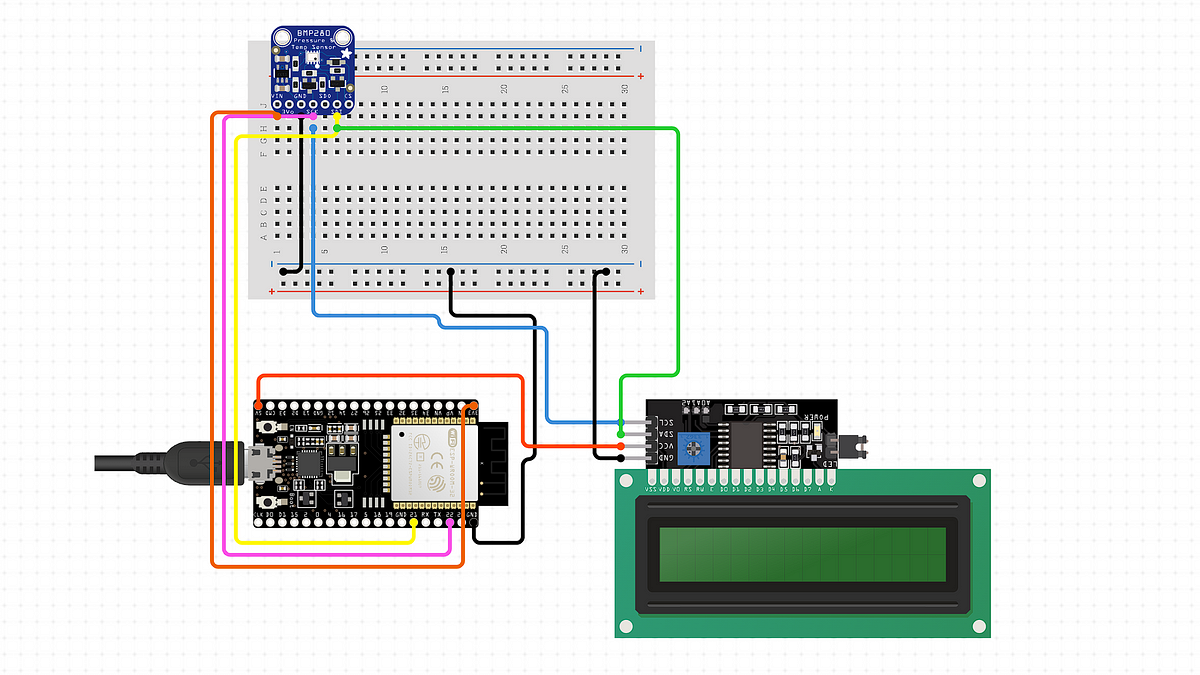
The key connections are:
- ESP32 SCL pin to the SCL pin of all slave devices.
- ESP32 SDA pin to the SDA pin of all slave devices.
- ESP32 GND to the GND of all slave devices.
- ESP32 3.3V to the VCC/VDD of all slave devices (ensure they are 3.3V compatible!).
You can use any free GPIO pins for SDA and SCL on the ESP32. Common choices are GPIO 21 (SDA) and GPIO 22 (SCL), but the GPIO matrix gives you full flexibility.
5. Wrapping I2C in a C++ Class
As we did with UART, we can elevate the C-style ESP-IDF code into a more structured and reusable C++ implementation. The goal is to create classes that hide the low-level configuration details and provide a simple interface for interaction.
Given the bus-device model of the modern API, a good C++ design would be:
- A
I2C_Busclass to represent the physical bus. Its constructor would take the pin configurations and calli2c_new_master_bus()to get a bus handle. - A
I2C_Deviceclass to represent a slave. Its constructor would take a reference to anI2C_Busobject and the device's address/speed, then calli2c_master_bus_add_device()to get a device handle. - The
I2C_Deviceclass would have methods likereadRegister,writeRegister, etc., which would call the underlying ESP-IDF functions likei2c_master_transmit_receive().
This approach provides excellent abstraction. In your main application, you would simply create a bus object once, and then create a device object for each sensor you want to talk to.
ESP-IDF C++ I2C Driver - EmbeddedTutorials
This article from EmbeddedTutorials demonstrates the concept of creating a C++ wrapper for I2C. While the code uses an older, deprecated version of the ESP-IDF I2C API, the class structure and the motivation behind it are still very relevant.
Skim through the 'Define the C++ I2C class' and 'Implement the C++ I2C class' sections. Focus on the structure of the I2c class: Private member variables to hold configuration. A constructor to set up initial parameters. An InitMaster method to configure the hardware. Public methods like ReadRegister and WriteRegister that hide the complex API calls. Important: The article uses i2c_param_config() and i2c_driver_install(). These are part of the legacy API. A modern implementation, which you should aim for, would adapt this class structure to use the i2c_new_master_bus() and i2c_master_bus_add_device() functions we've focused on in this lesson.
Conclusion
You have now learned the fundamentals of the I2C protocol and how to implement it on the ESP32. This is a huge step forward, opening the door to a vast ecosystem of advanced sensors and peripherals.
Key Takeaways:
- I2C is a synchronous, 2-wire bus (SDA/SCL) that can connect multiple slave devices to a single master.
- Each device has a unique 7-bit address, and communication is managed with START/STOP conditions and ACK/NACK bits.
- The modern ESP-IDF uses a bus-device model: first
i2c_new_master_busto configure the pins, theni2c_master_bus_add_devicefor each slave. - Reading a sensor register is typically a two-part transaction, perfectly handled by the
i2c_master_transmit_receivefunction. - Encapsulating I2C logic in C++ classes provides a clean, reusable, and abstract interface for your applications.
In the next lesson, we will explore the third major serial protocol: SPI (Serial Peripheral Interface). We'll see how it differs from I2C, offering higher speeds at the cost of more wiring, and when you might choose one over the other.