Hello and welcome back to our module on Advanced Motor Control.
In the previous lesson, we explored why the ESP32's Motor Control PWM (MCPWM) peripheral is the superior choice for driving motors compared to the general-purpose LEDC peripheral. We learned that MCPWM's key advantages lie in its dedicated hardware for generating complementary PWM signals, inserting dead-time, creating symmetric waveforms, and handling faults.
Today, we transition from the "why" to the "how." This lesson directly addresses the learning outcome: Configure the MCPWM peripheral to generate complementary PWM signals for an H-bridge. We will dissect the architecture of the MCPWM unit and walk through the C++ ESP-IDF code needed to configure its building blocks to produce these essential signals.
1. The MCPWM Architecture: A System of Building Blocks
Before writing code, it's crucial to understand the modular structure of the MCPWM peripheral. Think of it not as a single entity, but as a system of interconnected components that you configure and link together. Your experience in mechanical engineering with systems composed of distinct functional parts should make this approach feel quite natural.
This block diagram gives a high-level overview of the components we'll be working with.

To understand how to configure these, let's look at the main components you'll interact with in the ESP-IDF API.
Chapter 162: Motor Control Unit (MCPWM) Fundamentals
The following article, which we also used in the last lesson, provides a clear breakdown of the MCPWM architecture from the perspective of the modern ESP-IDF v5.x API. This will be our guide.
Please read the section titled 'MCPWM Architecture (ESP-IDF v5.x Perspective)'. Focus on understanding the role of each of the following components: Timers, Operators, Comparators, and Generators. We will be creating and connecting each of these in our code.
Based on your reading, here’s a summary of the roles these components play in our goal of generating complementary PWM:
- Timers (
mcpwm_timer_handle_t): This is the time base or "heartbeat" of the system. It counts continuously, providing the reference against which all events are timed. We will configure it to set the PWM frequency and to useMCPWM_TIMER_COUNT_MODE_UP_DOWNfor a symmetric (center-aligned) waveform, which is ideal for motor control. - Operators (
mcpwm_operator_handle_t): An operator is a control unit that connects a specific timer to one or more generators. Think of it as the central hub for one set of PWM outputs. This is also where we will apply overarching settings like dead-time. - Comparators (
mcpwm_cmpr_handle_t): A comparator's job is to hold a value (the "compare value") that corresponds to the desired duty cycle. It constantly compares this value to the timer's count. When the timer's count matches the compare value, it triggers a "compare event". - Generators (
mcpwm_gen_handle_t): This is the final output stage, directly controlling a GPIO pin. A generator is configured to take specific actions (set pin high, low, or toggle) in response to events from its associated timer (e.g., timer reaches zero) and comparator (e.g., a compare event occurs). Each operator typically has two generators (A and B) to create a complementary pair of signals.
The core of MCPWM programming is configuring each of these objects and then linking them together: Generator → Operator → Timer.
2. The Configuration Workflow in C++
Now, let's translate that architecture into a sequence of steps using the ESP-IDF. The process involves creating handles for each component and configuring them.
- Configure and Create Timer: Define the frequency and count mode.
- Configure and Create Operator: Create an operator and connect it to the timer from step 1.
- Configure and Create Comparator: Create a comparator and associate it with the operator from step 2.
- Configure and Create Generators: Create two generators (A and B) and associate them with the operator. Assign a GPIO pin to each.
- Define Generator A's Actions: Tell Generator A how to behave based on timer and comparator events to create the primary PWM waveform.
- Apply Dead-Time and Inversion: Configure the operator's dead-time module. This is where we tell the hardware to automatically generate the complementary signal on Generator B.
- Enable and Start: Enable the timer to start PWM generation.
3. Practical Implementation: Generating Complementary Signals
We'll now examine a complete code example that implements the workflow above to generate a 20kHz symmetric, complementary PWM signal pair suitable for one leg of an H-bridge.
Chapter 162: Motor Control Unit (MCPWM) Fundamentals
The circuitlabs.net article provides an excellent, self-contained example for generating complementary PWM with dead-time. We will analyze this code block by block.
Please review the code in 'Example 2: Complementary PWM with Dead-Time for Half-Bridge'. Don't worry about memorizing every line; focus on matching the code blocks to the architectural components we just discussed (Timer, Operator, etc.).
Let's break down the key parts of that example.
Timer Configuration
mcpwm_timer_config_t timer_config = {
    .group_id = 0,
    .clk_src = MCPWM_TIMER_CLK_SRC_DEFAULT,
    .resolution_hz = DT_TIMER_RESOLUTION_HZ, // e.g., 1,000,000 Hz (1 MHz)
    .period_ticks = DT_PWM_PERIOD_TICKS,     // e.g., 25
    .count_mode = MCPWM_TIMER_COUNT_MODE_UP_DOWN, // Symmetric PWM
};
ESP_ERROR_CHECK(mcpwm_new_timer(&timer_config, &dt_timer));
Here, we set the timer's "tick" rate (resolution_hz) and how many ticks make up one period (period_ticks). For symmetric (UP_DOWN) mode, the timer counts from 0 up to period_ticks and then back down to 0. Therefore, the PWM frequency is calculated as:
For the example values: 1,000,000 / (2 * 25) = 20,000 Hz or 20kHz.
Operator and Comparator Configuration
// Create Operator and connect to timer
mcpwm_operator_config_t oper_config = { .group_id = 0 };
ESP_ERROR_CHECK(mcpwm_new_operator(&oper_config, &dt_oper));
ESP_ERROR_CHECK(mcpwm_operator_connect_timer(dt_oper, dt_timer));

// Create Comparator
mcpwm_comparator_config_t comp_config = { .flags.update_cmp_on_tez = true };
ESP_ERROR_CHECK(mcpwm_new_comparator(dt_oper, &comp_config, &dt_comparator));

// Set initial duty cycle (e.g., 50%)
ESP_ERROR_CHECK(mcpwm_comparator_set_compare_value(dt_comparator, DT_PWM_PERIOD_TICKS / 2));
This is straightforward: we create an operator, link it to our timer, and then create a comparator linked to that operator. We set an initial duty cycle by providing a compare_value.
Test your understanding!
You've configured an MCPWM timer with a resolution_hz of 1,000,000 (1MHz) and a period_ticks of 1000 in UP_DOWN count mode. To generate a symmetric PWM signal with a 40% duty cycle, what value should you pass to mcpwm_comparator_set_compare_value()?
Show answer
The value should be 400.
In UP_DOWN count mode, the total period consists of 2 * period_ticks. The active time of the pulse is determined by 2 * compare_value for a pulse centered around the peak.
Therefore, the duty cycle is calculated as:
Duty Cycle = (2 * compare_value) / (2 * period_ticks) = compare_value / period_ticks.
To get a 40% duty cycle (0.4):compare_value = 0.4 * period_ticks = 0.4 * 1000 = 400.
Generator Configuration and Actions
This is where the waveform is defined. We create two generators, dt_generator_a and dt_generator_b, assigning each to a physical GPIO pin.
mcpwm_generator_config_t gen_a_config = { .gen_gpio_num = PWM0A_GPIO_NUM };
ESP_ERROR_CHECK(mcpwm_new_generator(dt_oper, &gen_a_config, &dt_generator_a));

mcpwm_generator_config_t gen_b_config = { .gen_gpio_num = PWM0B_GPIO_NUM };
ESP_ERROR_CHECK(mcpwm_new_generator(dt_oper, &gen_b_config, &dt_generator_b));
Crucially, we only need to define the logic for one of the generators. We'll define a standard active-high symmetric PWM on Generator A. A simple way to achieve this is:
- Go HIGH when the timer, counting down, matches the compare value.
- Go LOW when the timer, counting up, matches the compare value.
This creates a pulse that is centered around the peak count of the timer. The example code uses a slightly different but valid set of actions. The key takeaway is that you define the behavior of the primary signal (PWMxA) here.
The Magic: Creating the Complementary Signal
So how do we create the second, inverted signal on Generator B without defining a whole new set of opposite actions? This is handled automatically by the dead-time module.
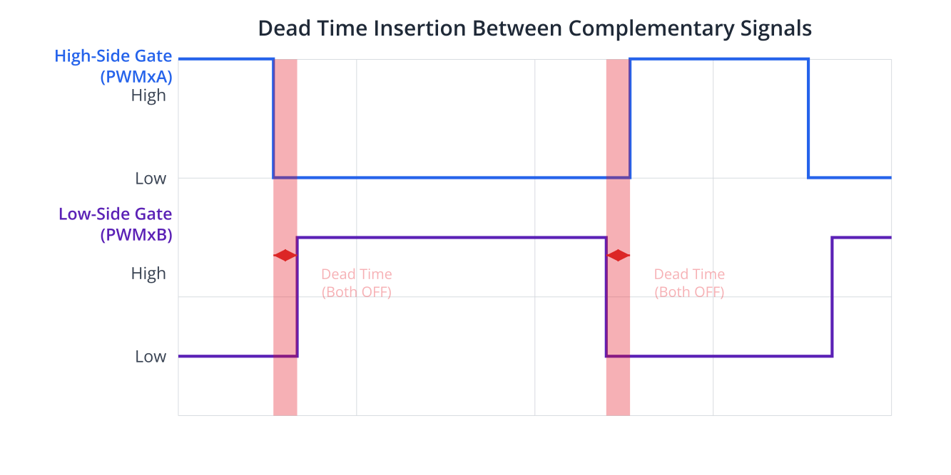
Look at the dead-time configuration in the example:
mcpwm_dead_time_config_t dt_config = {
    .posedge_delay_ticks = DEAD_TIME_RISE_EDGE_TICKS, // e.g., 2
    .negedge_delay_ticks = DEAD_TIME_FALL_EDGE_TICKS, // e.g., 3
    .flags.invert_output_a = false, // PWMxA is our primary active-high signal
    .flags.invert_output_b = true,  // PWMxB is the active-low complementary signal
};
ESP_ERROR_CHECK(mcpwm_operator_apply_deadtime(dt_oper, &dt_config));
The most important line for today's lesson is .flags.invert_output_b = true. By setting this flag, you instruct the MCPWM hardware to:
- Take the signal being generated for PWMxA.
- Invert it to create the base signal for PWMxB.
- Automatically insert the specified dead-time delays on the rising and falling edges of both signals to ensure they never overlap.
This single configuration step replaces complex software logic and guarantees perfect, hardware-timed complementary outputs. We configure one signal and get the second, complementary one for free.
Conclusion
In this lesson, we bridged the gap between theory and practice. You learned how the MCPWM peripheral's modular architecture allows for powerful and flexible PWM generation.
Key Takeaways:
- MCPWM is configured by creating and connecting C++ objects that represent its hardware blocks: Timers, Operators, Comparators, and Generators.
- Symmetric PWM, configured with
MCPWM_TIMER_COUNT_MODE_UP_DOWN, provides smoother and more efficient motor control. - You only need to define the output actions for one generator (e.g., PWMxA) to create the primary waveform.
- The complementary signal (PWMxB) is generated automatically by configuring the dead-time module with the
.flags.invert_output_b = trueflag.
You now have the fundamental knowledge to set up the MCPWM peripheral for H-bridge control. In our next lesson, we will focus specifically on the dead-time configuration itself. We'll learn how to calculate the appropriate dead-time values for your specific motor driver and how to prevent the dangerous condition of H-bridge shoot-through.