Hello! Welcome back to our module on Advanced Motor Control.
In our previous lesson, we established a solid theoretical foundation for the H-bridge motor driver. We explored how it uses a four-switch configuration to reverse current flow for directional control, the importance of flyback diodes, and how Pulse Width Modulation (PWM) is used to manage motor speed.
Today, we transition from theory to practice. This lesson is about applying that knowledge to a real-world circuit. Our goal is to control a DC motor's speed and direction using an ESP32, an H-bridge driver, GPIO pins for direction, and the ESP32's powerful LEDC peripheral for PWM speed control. By the end of this lesson, you will have a functional circuit and the C++ code to make a motor spin, change direction, and vary its speed.
1. The Hardware: ESP32 and the L298N H-Bridge
While the ESP32 can generate control signals, it cannot directly power a motor. Microcontroller pins have very low current limits (typically a few tens of milliamps), whereas a small DC motor can easily draw hundreds of milliamps, or even several amps when starting up or under load. Attempting to power a motor directly from a GPIO pin will damage the ESP32.
This is where a motor driver comes in. It acts as an intermediary, taking low-current control signals from the ESP32 and using them to switch a much higher-current power source for the motor. For this lesson, we will use the L298N, a classic and widely available dual H-bridge driver. While it's based on older BJT technology and is less efficient than modern MOSFET drivers, its robustness and clear pin functions make it excellent for learning.
To understand how to connect it, let's look at its pinout and a complete wiring diagram.
How to Control DC Motors Using ESP32 and L298N Module
The following article from Last Minute Engineers provides an excellent breakdown of the L298N module, its pins, and how to wire it to an ESP32.
Please read the sections titled 'L298N Motor Driver Module Pinout' and 'Wiring an L298N Motor Driver Module to an ESP32'. Focus on: The function of each pin group: Power, Motor Output, Direction Control (IN1-IN4), and Speed Control (ENA/ENB). The importance of removing the jumpers on ENA and ENB to allow for PWM speed control. The final wiring diagram showing the connections between the ESP32, L298N, motor, and an external power supply.
Based on the article, here is a summary of the key connections for one motor (Motor A):
- Power: Connect an external power supply (e.g., a 6V-12V battery pack) to the L298N's screw terminals (VS and GND). Crucially, connect the L298N's GND pin to one of the ESP32's GND pins. All components in a circuit must share a common ground.
- Motor: Connect your DC motor to the
OUT1andOUT2screw terminals. - Direction Control: Connect the L298N's
IN1andIN2pins to two standard GPIO pins on the ESP32 (e.g., GPIO 27 and 26). - Speed Control: Remove the jumper from the
ENApin. ConnectENAto a PWM-capable GPIO pin on the ESP32 (e.g., GPIO 14).

2. Software: Direction Control with GPIO
As we learned, the H-bridge's direction is controlled by the logic levels on its input pins. For the L298N, the IN1 and IN2 pins control the direction of Motor A according to the following logic:
| IN1 | IN2 | Motor State |
|---|---|---|
| LOW | LOW | Coast (motor freewheels to a stop) |
| HIGH | LOW | Forward (or one direction) |
| LOW | HIGH | Backward (or the opposite direction) |
| HIGH | HIGH | Brake (motor stops quickly) |
In C++, we implement this using simple digitalWrite() commands. In our setup() function, we configure the direction pins as outputs:
// Define pins for Motor A
#define ENA_PIN 14  // Speed control (PWM)
#define IN1_PIN 27  // Direction control 1
#define IN2_PIN 26  // Direction control 2

void setup() {
  pinMode(IN1_PIN, OUTPUT);
  pinMode(IN2_PIN, OUTPUT);
  // ... more setup to come
}
Then, to drive the motor forward, we would write:
digitalWrite(IN1_PIN, HIGH);
digitalWrite(IN2_PIN, LOW);
3. Software: Speed Control with the LEDC Peripheral
To control the motor's speed, we supply a PWM signal to the ENA pin. A higher duty cycle means higher average voltage and faster speed.
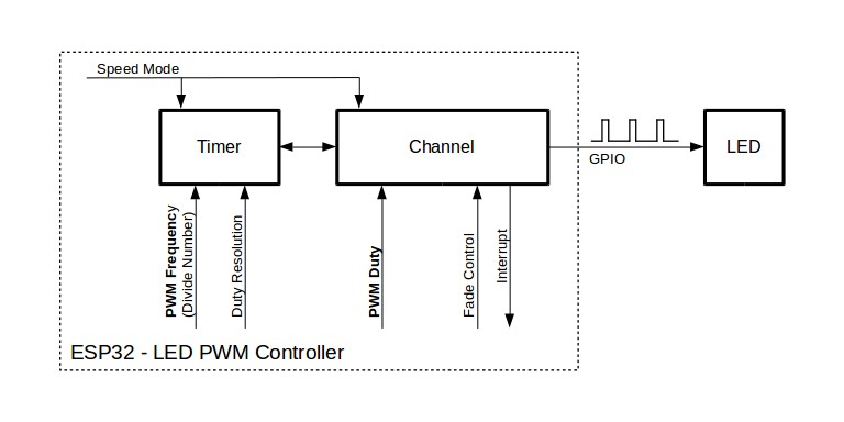
The ESP32 has a dedicated hardware peripheral called the LEDC (LED Control) PWM Controller, which is perfect for this task. It's highly configurable and more powerful than the standard analogWrite() function you might be used to from other platforms.
The LEDC peripheral is configured using two main concepts: Timers and Channels.
-
LEDC Timer: Defines the fundamental properties of the PWM signal. The two most important are:
- Frequency: How many pulses per second (Hz). A common range for motors is 1 kHz to 20 kHz.
- Resolution: The number of bits used to represent the duty cycle. An 8-bit resolution gives you 256 steps (0-255), while a 10-bit resolution gives 1024 steps (0-1023).
-
LEDC Channel: This acts as the link between a configured timer and a physical GPIO pin. You assign a channel to a pin and then command that channel to output a specific duty cycle.
In the Arduino IDE for ESP32, we use three main functions to control the LEDC peripheral:
ledcSetup(channel, frequency, resolution_bits): Configures a channel with a specific frequency and resolution. This sets up both the timer and channel properties.ledcAttachPin(gpio_pin, channel): Connects a GPIO pin to the configured channel.ledcWrite(channel, duty_cycle): Sets the output duty cycle on the specified channel. Theduty_cyclevalue depends on the resolution (e.g., 0-255 for 8-bit).
Let's see how to configure this in code.
// Define PWM properties
#define PWM_FREQUENCY 5000 // 5 kHz
#define PWM_CHANNEL   0    // Use LEDC channel 0
#define PWM_RESOLUTION 8   // 8-bit resolution (0-255)

void setup() {
  // ... pinMode configuration from before ...

  // 1. Configure the LEDC channel
  ledcSetup(PWM_CHANNEL, PWM_FREQUENCY, PWM_RESOLUTION);

  // 2. Attach the channel to the GPIO pin
  ledcAttachPin(ENA_PIN, PWM_CHANNEL);
}
Now, to set the motor to half speed, we would write a duty cycle of approximately 127 (since 255 is full speed for an 8-bit resolution):
// Set motor to roughly 50% speed
ledcWrite(PWM_CHANNEL, 127);
Test your understanding!
If you configured the LEDC peripheral with a 10-bit resolution (PWM_RESOLUTION = 10), what value would you pass to ledcWrite() to run the motor at approximately 25% speed?
Show answer
A 10-bit resolution provides values from 0 to 1023 (2^10 - 1).
25% of the maximum speed would be approximately 0.25 * 1023 = 255.75.
So, you would write ledcWrite(PWM_CHANNEL, 256); to get a 25% duty cycle.
4. Putting It All Together: A Complete Example
Let's combine these concepts into a complete sketch that demonstrates full speed and direction control. The following code will make the motor accelerate forward, run for two seconds, decelerate, stop, and then repeat the process in reverse.
This is a great starting point for any project involving DC motors.
/*
  ESP32 DC Motor Control with L298N
  - Direction controlled by GPIO pins
  - Speed controlled by LEDC PWM peripheral
*/

// Motor A connections
#define ENA_PIN 14  // ESP32 pin connected to L298N ENA
#define IN1_PIN 27  // ESP32 pin connected to L298N IN1
#define IN2_PIN 26  // ESP32 pin connected to L298N IN2

// PWM properties
#define PWM_FREQUENCY 5000 // PWM frequency in Hz
#define PWM_CHANNEL   0    // LEDC channel (0-15)
#define PWM_RESOLUTION 8   // Duty cycle resolution (1-16 bits)

// The maximum duty cycle value depends on the resolution.
// For 8-bit, this is 2^8 - 1 = 255.
const int MAX_DUTY_CYCLE = (1 << PWM_RESOLUTION) - 1;

void setup() {
  // Set motor control pins as outputs
  pinMode(IN1_PIN, OUTPUT);
  pinMode(IN2_PIN, OUTPUT);

  // Configure the LEDC PWM channel
  ledcSetup(PWM_CHANNEL, PWM_FREQUENCY, PWM_RESOLUTION);

  // Attach the PWM channel to the ENA pin
  ledcAttachPin(ENA_PIN, PWM_CHANNEL);

  Serial.begin(115200);
  Serial.println("Motor control test starting...");
}

void loop() {
  // --- FORWARD ---
  Serial.println("Moving Forward");
  // Set direction to forward
  digitalWrite(IN1_PIN, HIGH);
  digitalWrite(IN2_PIN, LOW);

  // Accelerate from 0 to max speed
  for (int dutyCycle = 0; dutyCycle <= MAX_DUTY_CYCLE; dutyCycle++) {
    ledcWrite(PWM_CHANNEL, dutyCycle);
    delay(10);
  }

  // Run at full speed for 2 seconds
  delay(2000);

  // Decelerate from max speed to 0
  for (int dutyCycle = MAX_DUTY_CYCLE; dutyCycle >= 0; dutyCycle--) {
    ledcWrite(PWM_CHANNEL, dutyCycle);
    delay(10);
  }

  // --- STOP ---
  Serial.println("Stopping");
  // Set pins to LOW to coast to a stop
  digitalWrite(IN1_PIN, LOW);
  digitalWrite(IN2_PIN, LOW);
  ledcWrite(PWM_CHANNEL, 0);
  delay(1000); // Pause for 1 second

  // --- REVERSE ---
  Serial.println("Moving Backward");
  // Set direction to reverse
  digitalWrite(IN1_PIN, LOW);
  digitalWrite(IN2_PIN, HIGH);

  // Accelerate from 0 to max speed
  for (int dutyCycle = 0; dutyCycle <= MAX_DUTY_CYCLE; dutyCycle++) {
    ledcWrite(PWM_CHANNEL, dutyCycle);
    delay(10);
  }

  // Run at full speed for 2 seconds
  delay(2000);

  // Decelerate from max speed to 0
  for (int dutyCycle = MAX_DUTY_CYCLE; dutyCycle >= 0; dutyCycle--) {
    ledcWrite(PWM_CHANNEL, dutyCycle);
    delay(10);
  }

  // --- STOP ---
  Serial.println("Stopping");
  digitalWrite(IN1_PIN, LOW);
  digitalWrite(IN2_PIN, LOW);
  ledcWrite(PWM_CHANNEL, 0);
  delay(1000); // Pause for 1 second
}
Now it's your turn. Wire up your circuit, upload this code to your ESP32, and watch your motor come to life! Open the Serial Monitor to see the program's progress.
Conclusion
Congratulations! You have successfully bridged the gap between theory and practice. You've learned how to interface an ESP32 with an H-bridge motor driver and write C++ code to precisely control a DC motor.
Key Takeaways:
- A motor driver (like the L298N) is essential to safely power a motor from a microcontroller.
- Direction control is achieved by setting two GPIO pins (
IN1,IN2) toHIGHorLOW. - Speed control is achieved by sending a PWM signal to the driver's enable pin (
ENA). - The ESP32's LEDC peripheral is a powerful and flexible tool for generating PWM signals.
- Configuration involves setting up an LEDC channel with a desired frequency and resolution, attaching it to a pin, and then writing a duty cycle value to it.
In our next lesson, we will explore the advantages of the MCPWM (Motor Control PWM) peripheral. While the LEDC is excellent for simple PWM, the MCPWM is a specialized peripheral designed specifically for advanced motor control applications, offering features like complementary outputs and dead-time insertion, which are critical for building more efficient and robust H-bridges.