Hello and welcome! We're now diving into a new major topic area: Enterprise Wireless Networking. In the previous module, we finalized our look at IP Services by configuring SNMP for network monitoring. Now, we shift our focus to the technologies that enable mobility and untethered access, a critical component of any modern enterprise network.
This lesson begins our journey into wireless with the foundational learning outcome: Analyze the components and connectivity of a centralized Cisco wireless LAN architecture (AireOS/IOS-XE).
We will break down the fundamental architecture that underpins most enterprise Wi-Fi deployments. You'll learn about the key building blocks—the Wireless LAN Controller (WLC) and Access Points (APs)—and the protocol that connects them. We'll also compare Cisco's two main WLC operating systems: the legacy AireOS and the modern IOS-XE platform used in Catalyst 9800 controllers. As a solutions engineer, understanding these architectures is crucial for designing, deploying, and troubleshooting wireless networks for your customers.
1. The Centralized Wireless Architecture
In a centralized architecture, all management and control functions for the wireless network are consolidated into one or more WLCs. Lightweight Access Points (LAPs) are deployed throughout the enterprise, and they communicate with the central WLC to download their configuration and forward client traffic.
This model is built on a concept called Split-MAC Architecture. The "MAC" here refers to the Media Access Control functions defined in the 802.11 standard. In a Split-MAC model, these functions are divided between the AP and the WLC:
- The AP handles real-time, time-sensitive functions:
- Beacon generation and probing
- Packet acknowledgments and retransmissions
- Frame queuing and prioritization
- The WLC handles management-intensive functions:
- Authentication and association
- Policy enforcement (QoS, ACLs)
- Radio Resource Management (RRM)
This division of labor allows the APs to be simple and "lightweight," while the WLC provides centralized intelligence and control. To see a high-level overview of this model, please watch the following short video segment.
Wi-Fi Deployment Models Overview - Cisco CCNP ENCOR 350-401
This video from MixedNetworks introduces several wireless deployment models. We'll focus on the centralized model, which is the cornerstone of this lesson.
Watch the segment from 00:40 to 01:44. Pay attention to how the AP and WLC are placed in the network and the general path of client traffic.
2. CAPWAP: The Connecting Tunnel
The communication protocol that enables the Split-MAC architecture is CAPWAP (Control and Provisioning of Wireless Access Points). CAPWAP creates a secure tunnel between each AP and the WLC, allowing them to exchange control messages and client data.
The CAPWAP tunnel consists of two distinct channels:
- CAPWAP Control: Uses UDP port 5246. This channel carries management traffic, such as configuration updates, RRM information, and AP heartbeats. It is always encrypted using DTLS.
- CAPWAP Data: Uses UDP port 5247. This channel encapsulates the actual wireless client data frames, tunneling them from the AP to the WLC. By default, this traffic is not encrypted within the tunnel, but DTLS encryption can be enabled if required.
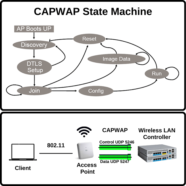
AP Discovery and Join Process
For an AP to establish a CAPWAP tunnel, it must first discover and select a WLC. This is a critical part of the "connectivity" aspect of our learning outcome. The AP follows a specific sequence of steps to find available controllers.
To understand this process in detail, please watch the following video.
AP Discovery & Join Processes - Cisco CCNP ENCOR 350-401
This video, also from MixedNetworks, provides a clear and detailed explanation of the AP discovery and join process. It walks through each method an AP uses to find a controller and the logic it uses to select one.
Watch from the beginning to 05:31. Focus on two key phases: Discovery Phase (0:00 - 2:35): Note the different methods the AP uses to discover WLCs (L3 broadcast, local storage, DHCP option 43, DNS, manual). Join Phase (2:35 - 5:31): Understand the criteria an AP uses to choose a WLC from the discovered list (previously joined, master controller, least loaded).
3. Architectural Components: AireOS vs. IOS-XE (Catalyst 9800)
While the underlying principles of Split-MAC and CAPWAP are the same, the way you configure the logical components of the architecture differs significantly between Cisco's legacy AireOS and modern IOS-XE platforms. The CCNP ENCOR exam requires you to be familiar with both, but places a strong emphasis on the new IOS-XE model.
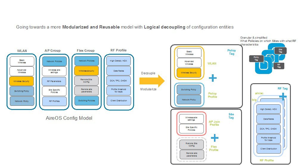
As the image shows, the Catalyst 9800 (running IOS-XE) replaces constructs like AP Groups and FlexConnect Groups with a more modular and flexible system of Profiles and Tags.
- Profiles are configuration "building blocks" that define a specific set of attributes (e.g., SSID settings, radio behavior, VLAN assignments).
- Tags are used to link these profiles together and apply the resulting configuration to one or more APs.
Each AP on a Catalyst 9800 controller is assigned three tags to receive its complete configuration:
- Policy Tag
- Site Tag
- RF Tag
To get a comprehensive understanding of this new model and how it relates to the older AireOS constructs, please read the following article.
Demystifying the Cisco Catalyst 9800 Configuration Model
This article from World Wide Technology, 'Demystifying the Cisco Catalyst 9800 Configuration Model', is an excellent resource for understanding the new architecture. It directly compares the old and new models, making the transition much clearer.
Read from the section 'Comparing and Contrasting AireOS to Cisco Catalyst 9800' down to the end of the 'Radio Configuration' section. Focus on: WLAN Configuration: How the Policy Tag binds a WLAN Profile (SSID settings) to a Policy Profile (VLAN, timers, QoS). Note the analogy: Policy Tag ≈ AireOS AP Group. Site Configuration: How the Site Tag defines an AP's location (Local vs. FlexConnect) and binds an AP Join Profile (CAPWAP timers, etc.). Note the analogy: Site Tag for a non-local site ≈ AireOS FlexConnect Group. Radio Configuration: How the RF Tag binds 2.4GHz and 5GHz RF Profiles to an AP.
Test your understanding!
In the Catalyst 9800 model, an administrator needs to broadcast two SSIDs (e.g., "Corporate" and "Guest") from a group of APs. The "Corporate" SSID should map clients to VLAN 10, and the "Guest" SSID should map clients to VLAN 20. Which tag would you use to apply this specific SSID-to-VLAN mapping policy to the APs?
Show answer
You would use a Policy Tag. The Policy Tag is responsible for binding WLAN Profiles (which define the SSIDs "Corporate" and "Guest") to their respective Policy Profiles (which define the VLAN assignments, 10 and 20). Applying this single Policy Tag to the APs makes them broadcast both SSIDs with the correct VLAN mappings.
4. A Deeper Look at Catalyst 9800 Components
Your role as a solutions engineer often involves understanding not just the logical configuration, but also the underlying platform architecture and how it scales. The Catalyst 9800 series includes a range of physical and virtual appliances designed for different deployment sizes.
Furthermore, the Catalyst 9800 has a multi-process software architecture. APs are load-balanced across multiple Wireless Network Controller Daemon (WNCd) processes running on the controller. This design is crucial for performance and scalability. The distribution of APs to these processes is based on the Site Tag. All APs sharing the same Site Tag are handled by the same WNCd process. This has significant design implications, especially for managing client roaming.
Cisco Catalyst 9800 Configuration Best Practices
This Cisco Live presentation deck contains best practices for Catalyst 9800 configuration. We will reference a few key slides to understand the hardware components and the WNCd architecture.
Please review the following slides from the PDF: Slide 11 ('Next-generation wireless infrastructure...'): Familiarize yourself with the different Catalyst 9800 models (9800-L, 9800-40, 9800-80, 9800-CL) and their scale in terms of AP and client count. Slide 131 ('Site Tags – Design considerations'): Understand the concept of WNCd processes and see the table showing how many instances run on each platform. Slide 132 ('Site Tags – AP to WNCd distribution'): This is a key slide. Note the rule: 'AP distribution to WNCd processes is based on Site Tag'. This explains why it's a best practice to create custom site tags to group APs within a roaming domain.
Understanding this link between Site Tags and WNCd processes is a perfect example of the deep technical knowledge that separates a configuration-focused approach from a design-focused one. For large-scale deployments, designing your Site Tags correctly is critical to ensuring seamless roaming and balanced controller performance.
Conclusion
In this lesson, we have analyzed the essential components and connectivity of a centralized Cisco wireless LAN architecture. You now have a solid foundation in the principles that govern modern enterprise Wi-Fi.
Key Takeaways:
- Centralized wireless architectures use a Split-MAC model, where real-time functions are on the AP and management functions are on the WLC.
- CAPWAP is the tunneling protocol that connects APs and WLCs, using UDP ports 5246 (Control) and 5247 (Data).
- APs discover WLCs through methods like DHCP Option 43 and DNS, then select one based on criteria like master-controller status or load.
- Legacy AireOS uses constructs like AP Groups to map WLANs to APs.
- Modern IOS-XE (Catalyst 9800) uses a more flexible model of Profiles and Tags (Policy, Site, RF) to apply configuration.
- On Catalyst 9800s, the Site Tag is a critical design element that influences how APs are load-balanced across internal WNCd processes for scalability.
Preview of the Next Lesson:
We've briefly mentioned different AP behaviors based on location, such as "Local" vs. "FlexConnect". In our next lesson, we will describe the different modes of operation for a Cisco Access Point. We'll take a much deeper dive into Local Mode, the default for a centralized design, and contrast it with FlexConnect, which is designed for remote and branch office deployments.