Hello! Welcome back to our course on the CCNP ENCOR exam.
In our last lesson, we focused on proactive measures, configuring STP protection features like Root Guard, BPDU Guard, and Loop Guard to prevent common causes of network instability. While these features are essential for a robust design, they don't prevent every possible issue. Misconfigurations, hardware failures, and physical layer problems can still lead to trouble.
This lesson addresses the reactive side: troubleshooting spanning tree topology issues, including blocked ports and suboptimal paths. We will build on your existing CCNA knowledge and solutions engineering experience to develop a systematic approach to diagnosing and resolving STP-related problems. By the end of this lesson, you'll be able to interpret STP states, identify the root cause of loops and inefficient traffic flow, and restore network stability.
1. A Systematic Approach to STP Troubleshooting
Effective troubleshooting isn't about guessing; it's a structured process. When faced with a potential STP issue, your experience as a solutions engineer will tell you that understanding the intended state is just as important as analyzing the current failed state.
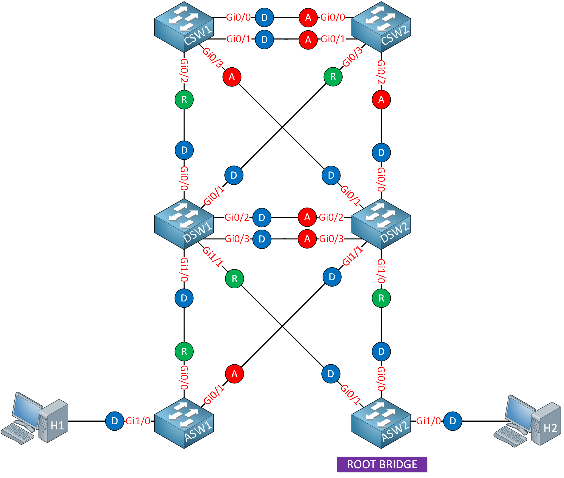
The core of STP troubleshooting revolves around this process:
- Define the Problem: Are you facing a catastrophic bridging loop (indicated by broadcast storms, high switch CPU, and widespread connectivity loss) or a performance issue caused by a suboptimal path?
- Understand the Intended Topology: Using your network diagrams, identify:
- Which switch should be the root bridge for each VLAN?
- Which links are redundant?
- Which ports are supposed to be in a blocking/alternate state?
- Gather Data: Use
showcommands on the affected switches to compare the actual state to the intended state. - Isolate the Cause: Based on the data, form a hypothesis and verify it.
The following document from Cisco outlines the common causes of STP failure and provides a framework for troubleshooting. We'll refer to it throughout this lesson.
Troubleshoot STP Problems and Related Design Considerations
Let's start with the foundational troubleshooting methodology. This Cisco document, 'Troubleshoot STP Problems and Related Design Considerations,' is a key resource for network professionals. We'll begin by looking at the general troubleshooting process.
Please read the section titled 'Troubleshoot a Failure'. Focus on the initial steps: 'Use the Diagram of the Network', 'Identify a Bridging Loop', and 'Restore Connectivity Quickly'. This establishes the high-level workflow we'll follow.
2. Troubleshooting Bridging Loops: The Case of the Forwarding Blocked Port
The most severe STP failure is a bridging loop. This almost always happens when a port that should be in a blocking (Alternate or Backup) state transitions incorrectly into a forwarding state.
The fundamental reason for this is BPDU loss. A switch keeps a port blocked only as long as it receives superior BPDUs on that port. If those BPDUs stop arriving, the switch will wait for the MaxAge timer to expire (20 seconds by default) and then transition the port through the listening and learning states into forwarding, creating a loop.
So, troubleshooting a loop often means asking: "Why did this port stop receiving BPDUs?"
Common Causes of BPDU Loss
The causes can range from simple physical issues to subtle misconfigurations. Let's examine the most common culprits.
Troubleshoot STP Problems and Related Design Considerations
The Cisco document we just looked at details several common causes of BPDU loss. We'll read through the most critical ones to understand the theory before seeing them in practical examples.
Please read the following subsections under 'Spanning Tree Protocol Failure': Duplex Mismatch: Understand how this leads to collisions and dropped BPDUs. Unidirectional Link: Grasp why this is particularly dangerous for fiber links. Packet Corruption: Note the connection to physical layer errors. Resource Errors: See how a high CPU can starve the STP process. For each, pay attention to the symptoms and the recommended verification commands like show interfaces.
As you just read, many problems originate at Layer 1 or from resource constraints. A key takeaway is that your first step in troubleshooting a loop should be to check the health of the physical interfaces involved using show interfaces. Look for:
- Runts, giants, CRC errors, and input errors (signs of packet corruption).
- Collisions and late collisions (classic signs of a duplex mismatch).
- High interface load (
txload,rxload).
Another common, but configuration-related, cause is the accidental filtering of BPDUs.
Troubleshooting Spanning Tree - NetworkLessons.com
This article from NetworkLessons.com provides a perfect, real-world example of how a misconfigured BPDU filter can cause a loop. It walks you through the diagnosis step-by-step.
Please read the section titled 'BPDUs Blocked'. Follow the author's logic: they observe designated ports where there should be blocked ports, hypothesize that BPDUs are being filtered, and then systematically check for causes until they find the spanning-tree bpdufilter enable command.
Test your understanding!
You are troubleshooting a network and discover a bridging loop. show spanning-tree on Switch-A reveals that its port Gi0/1, which connects to Switch-B, has transitioned to a Designated Forwarding state. You know this port should be an Alternate (blocking) port. Switch-B has a better Bridge ID and is closer to the root.
What is the most fundamental reason for Gi0/1's incorrect state, and what are two different potential root causes you would investigate first?
Show answer
- Fundamental Reason: The most fundamental reason is that Switch-A's Gi0/1 port has stopped receiving BPDUs from Switch-B.
- Potential Root Causes:
- Physical Layer Issue: Check for a duplex mismatch, a bad cable, or a unidirectional link failure on the connection between Switch-A and Switch-B. You would use
show interfaces Gi0/1on both switches to check for errors, collisions, and duplex settings. - Configuration Issue: Check if BPDU Filter is enabled on Switch-B's connecting port, which would prevent it from sending BPDUs to Switch-A. You would check the running configuration or use
show spanning-tree interface <interface> detail.
- Physical Layer Issue: Check for a duplex mismatch, a bad cable, or a unidirectional link failure on the connection between Switch-A and Switch-B. You would use
3. Troubleshooting Suboptimal Paths
A suboptimal path is a less severe but more common issue. The network is loop-free, but traffic is not flowing along the most efficient path—for example, it's using a 1Gbps link when a 10Gbps link is available but blocked by STP.
This happens when the STP algorithm's decisions don't align with your design goals. To fix it, you must influence the election process. Recall the STP decision hierarchy:
- Lowest Root Bridge ID -> Elects the Root Bridge
- Lowest Root Path Cost -> Elects the Root Port
- Lowest Sender Bridge ID
- Lowest Sender Port ID
Troubleshooting suboptimal paths means finding where the logic went wrong and correcting it by tuning STP parameters.
Scenario 1: Incorrect Root Port
This is the most common cause of a suboptimal path. A switch has multiple uplinks but chooses the slower or more congested one as its Root Port.
Troubleshooting Spanning Tree - NetworkLessons.com
The NetworkLessons article has an excellent scenario called 'Incorrect Root Port' that demonstrates this exact problem. It shows how an incorrect manual cost configuration can lead to a bad decision.
Please read the section 'Incorrect Root Port'. Notice how the engineer identifies the problem (a 10Mbit link is the root port instead of a 100Mbit link) and uses show spanning-tree to see that the costs are unexpectedly equal. This leads them to find the spanning-tree cost command misconfiguration.
The key to fixing this is to ensure the desired path has a lower cumulative root path cost. As you have a strong background in network engineering, you know this can be done by:
- Increasing the cost on the undesired link (
spanning-tree cost <value>). - Decreasing the cost on the desired link.
Scenario 2: Incorrect Root Bridge
If your entire traffic path seems inefficient, the problem might be more fundamental: the root bridge is in the wrong place. For instance, an access-layer switch at the edge of the network might have won the election by having the lowest MAC address. This pulls the logical center of the network to the edge, causing traffic to traverse the campus unnecessarily.
Solution: Manually set the bridge priority on your intended core or distribution switches to be lower than any other switch. As a best practice, you should explicitly set the root and backup root for every VLAN.
The following video explains how to manipulate priority, cost, and port-priority to tune your topology.
CCNP ENCOR // STP Tuning (Spanning Tree Protocol) // ENCOR 350-401 Complete Course
This video from Jeremy's IT Lab, 'STP Tuning,' covers the practical commands for influencing the STP topology. It's a great review of the tools you use to fix suboptimal paths.
Please watch from 02:52 to 13:21. This will cover: Modifying Bridge Priority (02:52): How to correctly set the root bridge and why the root primary macro can be unreliable. Modifying Port Cost (09:10): How to influence root port selection to direct traffic flow, reinforcing the concept from the NetworkLessons article.
4. Understanding Reconvergence
Finally, troubleshooting isn't always about a hard failure. Sometimes, the issue is slow performance after a topology change. When a link fails, STP must reconverge. This process involves Topology Change Notifications (TCNs), which instruct switches to shorten their MAC address aging time (from 300s to the forward delay, 15s) to flush out old entries. This causes temporary flooding of unicast frames, which can impact performance.
Furthermore, the time it takes to reconverge can vary significantly.
- 30 Seconds: If a switch loses its root port but has an alternate port receiving BPDUs, it can immediately switch to the new path. The 30-second delay comes from the listening (15s) and learning (15s) states.
- 50 Seconds: If a switch loses its only path to the root, it must wait for the MaxAge timer (20s) to expire before it even starts the listening (15s) and learning (15s) process. (20 + 15 + 15 = 50s).
Knowing these timers helps you understand and explain network behavior during a failure event.
CCNP ENCOR // STP Topology Changes (LAB) // ENCOR 350-401 Complete Course
To see this in action, let's watch a lab that demonstrates these different reconvergence scenarios. Understanding why one failure takes 30s and another takes 50s is a key piece of deep troubleshooting.
Please watch the segments from 08:55 to 13:34. Pay close attention to the CLI output and the explanation for: The 30-second reconvergence (08:55): When the switch has an alternative path ready. The 50-second reconvergence (10:52): When the MaxAge timer must expire first because the switch believes it has lost the root entirely.
To see these events live, you can use debug spanning-tree events. This will show you TCNs being sent and received, as well as port state transitions, which is invaluable for real-time troubleshooting.
Conclusion
In this lesson, we developed a structured methodology for tackling common STP issues. We've moved from simply understanding how STP works to diagnosing why it might fail or perform poorly.
Key Takeaways:
- Systematic Approach: Always start by understanding the intended topology before diving into
showcommands. - Bridging Loops = BPDU Loss: If you see a loop, your primary goal is to find out why a blocking port stopped receiving BPDUs. Suspect the physical layer first (duplex, cables), then check for configuration issues like BPDU filters.
- Suboptimal Paths = Incorrect Parameters: If traffic flow is inefficient, the cause lies in the STP parameters. The root bridge is in the wrong place (fix with priority), or the wrong port was chosen (fix with cost).
- Key Commands: Your primary tools are
show spanning-tree,show spanning-tree detail,show interfaces,show processes cpu, anddebug spanning-tree events.
Preview of the Next Lesson:
We have now concluded our deep dive into Layer 2 redundancy with Spanning Tree. We know how to build, secure, and troubleshoot it. Our next topic moves up the stack to Layer 3 to solve a different kind of redundancy problem: providing a redundant default gateway for end hosts. We will begin by analyzing the operation of the Hot Standby Router Protocol (HSRP).