Hello! Welcome back to our study of IP Services.
In our last lesson, we configured NTP to ensure all our network devices are synchronized to the same clock. This is crucial for management and troubleshooting. Today, we shift from a network utility protocol to a fundamental traffic delivery method: multicast.
This lesson addresses the learning outcome: Explain multicast fundamentals including IGMP operation and multicast addressing.
As a solutions engineer, you've likely encountered applications like corporate video streaming, IPTV, or financial data feeds. These are classic use cases for multicast, a technology designed for efficient one-to-many communication. Instead of sending the same data stream multiple times to each recipient (unicast) or flooding it to everyone on the network (broadcast), multicast intelligently delivers a single stream only to those who have requested it.
Today, we'll explore the core components that make this possible: how multicast traffic is addressed at both Layer 3 and Layer 2, and how the Internet Group Management Protocol (IGMP) allows devices to "tune in" to these streams.
1. The Case for Multicast: Beyond Unicast and Broadcast
To start, let's establish why multicast is necessary by comparing it to the other delivery methods.
Cisco Multicast Routing for CCNA, CCNP, and CCIE Candidates
This video from Kevin Wallace Training provides an excellent introduction by comparing unicast, broadcast, and multicast communication. It clearly illustrates the efficiency gains of multicast.
Watch the segment from 00:40 to 03:27. Focus on the distinct drawbacks of unicast (server/bandwidth overhead) and broadcast (unwanted traffic for uninvolved hosts) and how multicast offers the best of both worlds.
The key takeaway is that multicast conserves network bandwidth and reduces the processing load on both the source server and non-participating hosts. But for this to work, the network infrastructure—specifically the switches and routers—must be multicast-aware.
What happens if they aren't? The default behavior of a simple Layer 2 switch when it receives a multicast frame is to treat it like a broadcast and flood it out of all ports.
IGMP - Internet Group Management Protocol
To see this problem in action, let's watch a practical demonstration by Tall Paul Tech. This video shows a network being flooded with multicast traffic before any management protocols are enabled.
Watch from the beginning to 02:14. Observe how the switch ports light up and the packet capture is swamped with multicast video traffic, even on ports connected to devices that haven't requested the stream. This visualizes the problem that IGMP is designed to solve.
This flooding behavior negates the primary benefit of multicast. To prevent this, we need a mechanism for hosts to signal their interest to the network and for the network to intelligently forward the traffic. This brings us to the two pillars of multicast operation: multicast addressing and the Internet Group Management Protocol (IGMP).
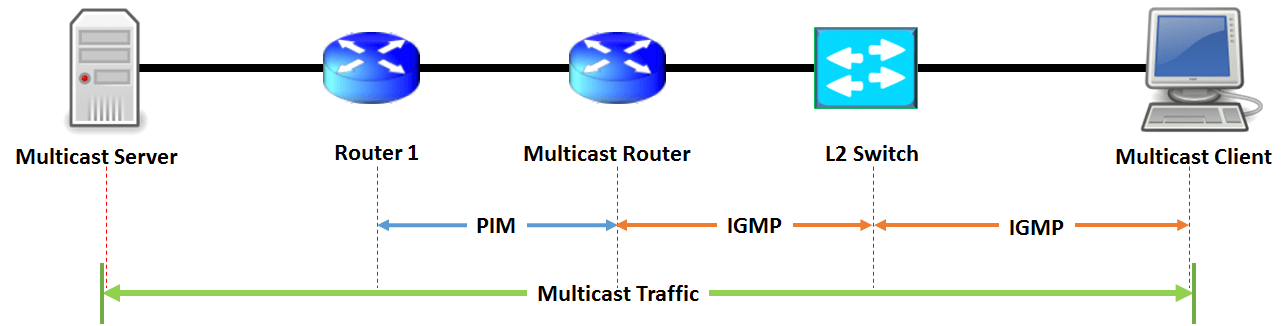
As the diagram shows, IGMP manages the relationship between receivers (clients) and their first-hop router. PIM, which we'll cover in the next lesson, handles routing the multicast traffic between routers across the enterprise. Today, our focus is on IGMP and the addressing that underpins it.
2. Multicast Addressing: Layers 3 and 2
Like any IP traffic, multicast relies on addressing at both Layer 3 (IP) and Layer 2 (MAC).
Layer 3: The Class D Address Space
The IANA has reserved the Class D address space for IPv4 multicast.
- Range: 224.0.0.0 to 239.255.255.255 (or 224.0.0.0/4).
- Usage: A multicast source sends packets to a multicast group address. The source address of the packet is always the server's own unicast IP address. Receivers "join" a group address to receive the traffic.
This Class D range is further subdivided for different purposes.
The NetAcad course material provides a clear breakdown of the multicast address space. We'll use it to understand the most important reserved ranges.
Please read pages 12 through 14. Pay close attention to Table 13-2, which lists the IANA assignments. Focus on understanding the purpose of these three key blocks: Local Network Control Block (224.0.0.0/24): Used for routing protocols (like OSPF, EIGRP) and other control plane traffic. These packets are link-local and are never forwarded by routers. Source Specific Multicast (SSM) Block (232.0.0.0/8): Used for applications where the receiver knows the IP address of the source it wants to receive from. Administratively Scoped Block (239.0.0.0/8): These are like the RFC 1918 private unicast addresses (e.g., 10.0.0.0/8). They are for use within a private enterprise and are not routed on the public internet.
For IPv6, multicast addresses are easily identified by the FF00::/8 prefix. While the structure is different, the concept remains the same: a dedicated address range for one-to-many communication.
Layer 2: Mapping IP to MAC
When a router forwards a multicast packet onto an Ethernet segment, it must place it in an Ethernet frame with a destination MAC address. How is this MAC address determined? It's derived directly from the Layer 3 multicast IP address.
- The IANA has reserved the MAC address prefix
01:00:5Efor IPv4 multicast. - The last 23 bits of the multicast IP address are appended to this prefix to form the complete 48-bit MAC address.

This mapping process has a very important consequence. An IPv4 multicast address has 28 variable bits (after the fixed 1110 prefix), but only 23 of those bits are copied to the MAC address. This means 5 bits of the IP address are ignored in the mapping.
Because of this, 32 (2^5) different IPv4 multicast group addresses will map to the exact same Layer 2 MAC address.
Cisco Multicast Routing for CCNA, CCNP, and CCIE Candidates
Let's return to the Kevin Wallace video for a clear, step-by-step walkthrough of this L3-to-L2 mapping and a demonstration of the overlap problem.
Watch the segment from 09:56 to 13:04. Follow the calculation for converting 224.1.10.10 to its MAC address. Then, pay close attention to the second example, which shows how 224.129.10.10 maps to the identical MAC address.
This overlap means a host's network card might receive multicast frames for a group it didn't subscribe to, simply because that group shares a MAC address with one it did subscribe to. The host's IP stack is then responsible for discarding these unwanted packets. This is an important detail to remember when troubleshooting multicast issues.
Test your understanding!
An application is using the administratively scoped multicast address 239.10.20.30. What is the corresponding Layer 2 multicast MAC address?
Hint:
- The fixed prefix is
01:00:5E. - The mapping ignores the first 9 bits of the IP address and uses the last 23 bits. This is equivalent to taking the last 23 bits of the last three octets.
- The second octet is
10(binary00001010). The crucial 5 bits are from the first octet. So, for the MAC address calculation, we are concerned with the value of the second octet modulo 128.10 mod 128 = 10. - Convert the relevant parts of the IP to hex:
10decimal is0Ahex.20decimal is14hex.30decimal is1Ehex.
Show answer
The IP address is 239.10.20.30.
- The fixed MAC prefix is
01:00:5E. - The last 23 bits of the IP address determine the rest of the MAC. We can look at the last three octets:
10.20.30. - The first bit of the second octet is ignored in the mapping. Here,
10is00001010in binary. The first bit is0, so it doesn't change the value. The value used is10. - We convert the relevant parts to hex:
10(decimal) =0A(hex)20(decimal) =14(hex)30(decimal) =1E(hex)
- Combining these parts:
0A:14:1E. - But we need to be careful with the second octet's first bit. The MAC address format is
01:00:5E:xx:yy:zzwherexxis derived from the second octet of the IP address. The range forxxcan only be00through7F. Since10is less than 128, the hex value is simply0A. - The final MAC address is
01:00:5E:0A:14:1E.
3. IGMP: Managing Group Membership
Now that we understand the addressing, how does a host actually "join" a group? This is the job of the Internet Group Management Protocol (IGMP).
IGMP is the communication protocol used between a multicast receiver (e.g., a PC) and its local multicast router. It allows the PC to say, "Hey, I want to receive traffic for group 239.1.1.1," and later, "I'm done with that traffic now."
IGMP Versions and Messages
There are three main versions of IGMP, with v2 being widely deployed and v3 adding important new features.
- IGMPv1 (Obsolete): Had a basic join mechanism but no explicit
Leavemessage. Routers had to wait for memberships to time out. - IGMPv2: Introduced the
Leave Groupmessage, allowing a host to proactively tell the router it is no longer interested. This significantly reduces unwanted traffic. - IGMPv3: Added support for Source-Specific Multicast (SSM). A host can now say, "I want to join group 239.1.1.1, but only if the traffic comes from server 10.5.5.5."
Cisco Multicast Routing for CCNA, CCNP, and CCIE Candidates
The Kevin Wallace video also provides a concise explanation of the different IGMP versions and their key messages.
Please watch from 13:04 to 17:41. Focus on: The concept of an IGMP Join (Membership Report). The Leave message introduced in IGMPv2. The source-filtering capability introduced in IGMPv3.
The IGMP Querier
On any network segment (like a VLAN), one multicast router is elected as the IGMP Querier. This router is responsible for periodically sending out General Query messages to the all-hosts address (224.0.0.1) asking, "Is anyone on this segment still interested in any multicast groups?"
If the querier doesn't receive a report for a specific group after a few queries, it assumes no one is listening anymore and tells the upstream PIM router to stop sending the traffic.
IGMP Snooping: Making Switches Smart
We saw earlier that a basic switch floods multicast traffic. IGMP Snooping is the feature that solves this. When enabled on a switch (it's often on by default on enterprise switches), the switch listens in ("snoops") on the IGMP messages exchanged between hosts and the router.
By doing this, the switch builds a table that maps multicast groups to the specific switch ports where interested receivers are located. When a multicast frame for group 239.1.1.1 arrives, the switch consults this table and forwards the frame only out of the ports that have an active listener for that group, rather than flooding it to everyone.
IGMP - Internet Group Management Protocol
Let's revisit the Tall Paul Tech demo to see the dramatic effect of enabling IGMP and the role of the querier.
Watch from 02:14 to 06:38. You will see: How enabling ip igmp on the switch immediately stops the flooding (this enables IGMP snooping). The membership timing out because there is no querier on the network. How configuring the switch to be an IGMP querier fixes the timeout issue by actively polling for members.
This demonstration perfectly ties together the concepts. IGMP snooping constrains multicast at Layer 2, and the IGMP querier is essential for maintaining the state of those multicast groups over time.
Conclusion
In this lesson, we have laid the essential groundwork for understanding multicast. You've learned how this efficient one-to-many communication method works, from the special addressing it uses to the protocol that manages group membership on a local network.
Key Takeaways:
- Multicast Purpose: To efficiently deliver a single stream of traffic from one source to many interested receivers, saving bandwidth and reducing host/server load.
- Layer 3 Addressing: Uses the IPv4 Class D range (
224.0.0.0/4) and the IPv6FF00::/8prefix. Key sub-ranges include link-local for control traffic and administratively scoped for private enterprise use. - Layer 2 Addressing: IPv4 multicast IPs are mapped to MAC addresses with the
01:00:5Eprefix. Due to an incomplete bit mapping, 32 IP addresses can map to a single MAC address. - IGMP: The protocol hosts use to report their interest in a multicast group to their local router. IGMPv2 added a
Leavemessage, and IGMPv3 added source-specific filtering. - IGMP Querier: A router on each LAN segment responsible for periodically checking for active group members.
- IGMP Snooping: A crucial Layer 2 feature on switches that prevents multicast flooding by learning which ports need to receive which multicast streams.
Preview of the Next Lesson:
We now understand how a host tells its local router, "I want to join this group." But how does that multicast traffic get from a server on the other side of the network to that local router in the first place? That is the job of a multicast routing protocol. In our next lesson, we will explore Protocol Independent Multicast (PIM) sparse mode, the most common method used to build these multicast distribution trees across an enterprise network.