Hello! Welcome back to our study of OSPF.
In our previous lesson, we established the fundamentals of OSPF: how it uses a variety of packet types to progress through the neighbor state machine, ultimately forming adjacencies to build and synchronize a complete network map, the Link-State Database (LSDB). We briefly introduced the Designated Router (DR) as the entity responsible for generating Type 2 Network LSAs on multi-access segments like Ethernet.
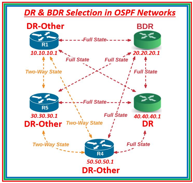
Today, we'll dive deep into that concept. A key challenge on multi-access networks is efficiency. If every router had to form a full adjacency with every other router, the number of adjacencies would grow exponentially (n(n-1)/2), creating excessive and redundant LSA flooding. OSPF solves this by electing a DR and a Backup Designated Router (BDR). All other routers on the segment (called DROthers) form full adjacencies only with the DR and BDR.
This lesson focuses on the learning outcome: Analyze the DR/BDR election process on multi-access networks. We will dissect the rules of the election, observe the process in action, and learn how, as network engineers, we can influence the outcome for a stable and predictable network.
1. The Role of DR and BDR
The DR and BDR act as the central point for communication on a multi-access network segment. Instead of all routers flooding updates to each other, DROthers send their updates to a single, well-known destination. The DR is then responsible for relaying that information to all other routers on the segment. The BDR listens in on the entire process and is ready to take over immediately if the DR fails.
This creates a more efficient "hub-and-spoke" communication model for LSA exchange on the segment, as illustrated below.
2. The Election Criteria
The DR/BDR election process is triggered when the first OSPF-enabled interface becomes active on a multi-access segment. The election is decided based on two criteria, in order of precedence:
- Highest OSPF Interface Priority: This is a configurable value from 0 to 255 on each router's interface. The default priority on Cisco routers is 1. A higher value is preferred.
- Highest Router ID: If the priorities are tied (as they are by default), the router with the highest Router ID wins the election. Since Router IDs must be unique, this serves as the ultimate tie-breaker.
A special case exists for priority: an interface configured with a priority of 0 is ineligible to participate in the election and can never become DR or BDR.
To begin, let's watch a short video that summarizes these rules.
The video 'OSPF DR/BDR Election' from telecomTech provides a concise overview of the rules that govern the election.
Please watch the segment from 01:38 to 03:14. Pay close attention to the two main criteria for election—OSPF priority and Router ID—and the role of priority 0.
3. The Election Process in Action: A Step-by-Step Analysis
One of the most important characteristics of the DR/BDR election is that it is non-preemptive. This means once a DR is elected, it will not be overthrown by a new router that comes online later, even if that new router has a higher priority or Router ID. This behavior is designed to promote network stability.
The following video provides an excellent demonstration of this principle. It shows how the election unfolds as routers are brought online one by one.
Designated Router // Backup Designated Router // DR BDR Election // Practical OSPF // Lesson 6
Let's see exactly how this election unfolds on a network segment. The video 'Designated Router // Backup Designated Router' from Practical Networking demonstrates the process step-by-step.
Watch the section from 01:27 to 06:09. Observe how the first router on the segment claims the DR role after its 'Wait Timer' expires. Notice that subsequent routers, even those with higher Router IDs, do not preempt the existing DR but will become the BDR if that role is available. This clearly illustrates the non-preemptive nature of the election.
As the video shows, when a router first initializes on a segment, it enters a "waiting" period (equal to the Dead Interval, 40 seconds by default on broadcast networks). During this time, it listens for Hello packets from an existing DR.
- If it hears from an established DR, it accepts that DR.
- If the wait timer expires and it hasn't heard from a DR, it will proceed with the election process, potentially claiming the DR role for itself.
4. Impact on Neighbor Adjacencies
A router's role—DR, BDR, or DROther—directly determines its final neighbor state with other routers on the segment. This is a crucial point that connects back to our previous lesson on the neighbor state machine.
- The DR and BDR form
FULLadjacencies with all other routers on the segment (including each other). - DROthers only form
FULLadjacencies with the DR and BDR. They remain in the2-WAYstate with all other DROthers.
Let's see how this is reflected in the router's command-line interface.
Designated Router // Backup Designated Router // DR BDR Election // Practical OSPF // Lesson 6
A router's role as DR, BDR, or DROther directly impacts its neighbor adjacency state. Let's see how this appears in the router's command line.
Watch from 06:09 to 08:31. The show ip ospf neighbor command output clearly shows that the DR and BDR have a FULL state with all neighbors, while DROthers have a FULL state only with the DR/BDR and remain in 2-WAY/DROTHER with other non-DR/BDR routers.
5. Controlling the Election
In a production network, relying on boot order to determine the DR is not a robust design. You will typically want your most powerful or centrally located routers to assume the DR and BDR roles. We can achieve this deterministically by manipulating the OSPF interface priority.
The best practice is to:
- Set a high priority (e.g., 100) on the interface of the desired DR.
- Set a slightly lower priority (e.g., 90) on the interface of the desired BDR.
- Leave other routers at the default of 1, or set their priority to 0 if you want to explicitly exclude them from the election.
This is configured in the interface configuration mode: ip ospf priority <0-255>
It's vital to remember that DR/BDR election is a per-interface, per-segment process. A single router can be the DR on one network segment, a BDR on another, and a DROTHER on a third.
The next segment of the video demonstrates how to configure these priorities.
Designated Router // Backup Designated Router // DR BDR Election // Practical OSPF // Lesson 6
In a production network, we can't leave the DR/BDR election to chance. This is achieved by manipulating the OSPF interface priority. This video segment shows how.
Watch from 08:31 to 12:01. Focus on how setting specific priority values forces a predictable outcome. Pay close attention to the special meaning of priority 0 and the clarification that DR/BDR status is a per-interface, not per-router, property.
Test your understanding!
You have four routers on an Ethernet segment, all with default OSPF priority. Their Router IDs are 1.1.1.1, 2.2.2.2, 3.3.3.3, and 4.4.4.4. If they all boot up at the same time, which router becomes the DR and which becomes the BDR?
Now, after the election is complete, you configure the router with RID 1.1.1.1 to have an OSPF priority of 255 on its interface. Does it become the new DR? Why or why not?
Show answer
Initially, since all priorities are equal (default of 1), the election is decided by the highest Router ID.
- DR: The router with RID 4.4.4.4 (highest RID).
- BDR: The router with RID 3.3.3.3 (second-highest RID).
After you change the priority on router 1.1.1.1 to 255, it does not become the new DR. The election is non-preemptive. The existing DR (4.4.4.4) will remain the DR as long as it is active. A new election will only be triggered if the current DR or BDR fails.
6. Analyzing LSA Flooding with a DR
With the DR/BDR roles established, we can analyze the LSA flooding process more precisely. OSPF uses two key multicast addresses for this:
- 224.0.0.5 (AllSPFRouters): All OSPF routers listen to this address.
- 224.0.0.6 (AllDRouters): Only the DR and BDR listen to this address.
The update process works as follows:
- A DROther needs to send an update. It sends the LSU packet to the destination multicast address 224.0.0.6. Only the DR and BDR receive this update.
- The DR receives the update and floods it to all routers on the segment by sending the LSU to the destination multicast address 224.0.0.5.
- All routers on the segment receive the update from the DR and update their LSDBs.
This process ensures that the DR is the single source of updates for the segment, preventing uncontrolled flooding between all routers.
Designated Router // Backup Designated Router // DR BDR Election // Practical OSPF // Lesson 6
The primary purpose of the DR is to manage LSA flooding. Let's analyze the exact flow of updates using the specific multicast addresses reserved for this purpose.
Watch the final section of the video from 12:01 to 15:40. Trace the path of an LSA update originating from a DROther, and contrast it with an update originating from the DR itself. Note the different multicast destination addresses used in each case.
Conclusion
Today we have performed a detailed analysis of the OSPF DR/BDR election process on multi-access networks. We've moved beyond simply knowing that it happens to understanding why it's necessary, how the rules are applied, and how we can engineer a predictable outcome.
Key Takeaways:
- Purpose: DR and BDRs are elected on multi-access networks (like Ethernet) to reduce the number of required adjacencies and optimize the LSA flooding process.
- Election Criteria: The election is won by the router with the highest OSPF interface priority. The highest Router ID is used as a tie-breaker. A priority of 0 makes a router ineligible.
- Non-Preemptive: To ensure stability, the election is non-preemptive. A new router will not force a re-election, even if it has superior criteria.
- Control: We can deterministically control the election by setting OSPF interface priorities, ensuring our desired routers take on the DR/BDR roles.
- Scope: The DR/BDR role is specific to a network segment and interface, not the entire router.
Preview of the Next Lesson:
Now that we have covered the core mechanics of how OSPF neighbors form adjacencies (Lesson 1) and manage communication on shared links (Lesson 2), we are ready to put this theory into practice. In our next lesson, we will move into hands-on configuration, focusing on how to configure and verify single-area OSPFv2 for IPv4 and OSPFv3 for IPv6.