Hello! In our last lesson, we mastered the process of drawing one-to-many (1:M) relationships, which are the workhorses of most database designs. You learned a systematic way to translate a business scenario into an accurate ERD using Crow's Foot notation.
Today, we'll continue building our diagramming skills by focusing on a less common but equally important relationship type: the one-to-one (1:1) relationship. While the drawing process will feel familiar, the key is understanding when and why to use a 1:1 relationship and how to represent its unique constraints correctly. This lesson will bring you one step closer to creating comprehensive database blueprints.
1. What is a One-to-One Relationship?
A one-to-one (1:1) relationship exists when a single record in one entity is linked to exactly one record in another entity, and vice-versa. Think of a PERSON and their PASSPORT; one person has one passport, and that one passport belongs to only that one person.
While it might seem that data in a 1:1 relationship could just be combined into a single table, there are specific design reasons to keep them separate. Let's explore the definition and the strategic value of this relationship type.
How To Model a One-To-One Relationship in a Database (And Why)
This video from Database Star provides a concise definition of a 1:1 relationship and explains the practical reasons for using one.
Please watch the first two sections of the video: Start with the definition of a one-to-one relationship. Continue with the explanation of why you would use one, focusing on the concepts of optional attributes and data from different sources.
The video highlighted two key reasons for using a 1:1 relationship:
- Separating Optional Data: If an entity has many attributes that are often empty (null) for most records, you can move those optional attributes into a separate table. This keeps your main table clean and can improve performance.
- Data Organization and Security: You might separate data for clarity, or to apply different security rules. For example, general employee data could be in one table, while sensitive payroll or health information is in a separate, more restricted table linked via a 1:1 relationship.
To solidify your understanding, let's look at some more real-world examples.
What Is a One to One Relationship in ERD? A Complete Guide
This article from Creately provides several clear, real-world examples of 1:1 relationships that will help you recognize them in business scenarios.
Read the section titled "Real-world examples of one-to-one relationships." As you read through the examples (Person ↔ Passport, User ↔ User Profile, etc.), think about why the designer might have chosen to split the information into two separate entities rather than one.
2. Drawing a One-to-One Relationship
The process for drawing a 1:1 relationship is the same one you learned for 1:M relationships. The only difference lies in the cardinality symbols you place at the ends of the relationship line. We will continue using Crow's Foot notation.
Cardinality Symbols for 1:1 Relationships
In a 1:1 relationship, the maximum cardinality on both sides is "one." The key symbols are:
||(One and Only One): This indicates a mandatory relationship. The entity instance must be related to exactly one instance in the other entity.|O(Zero or One): This indicates an optional relationship. The entity instance can be related to at most one instance, but it can also be related to zero.
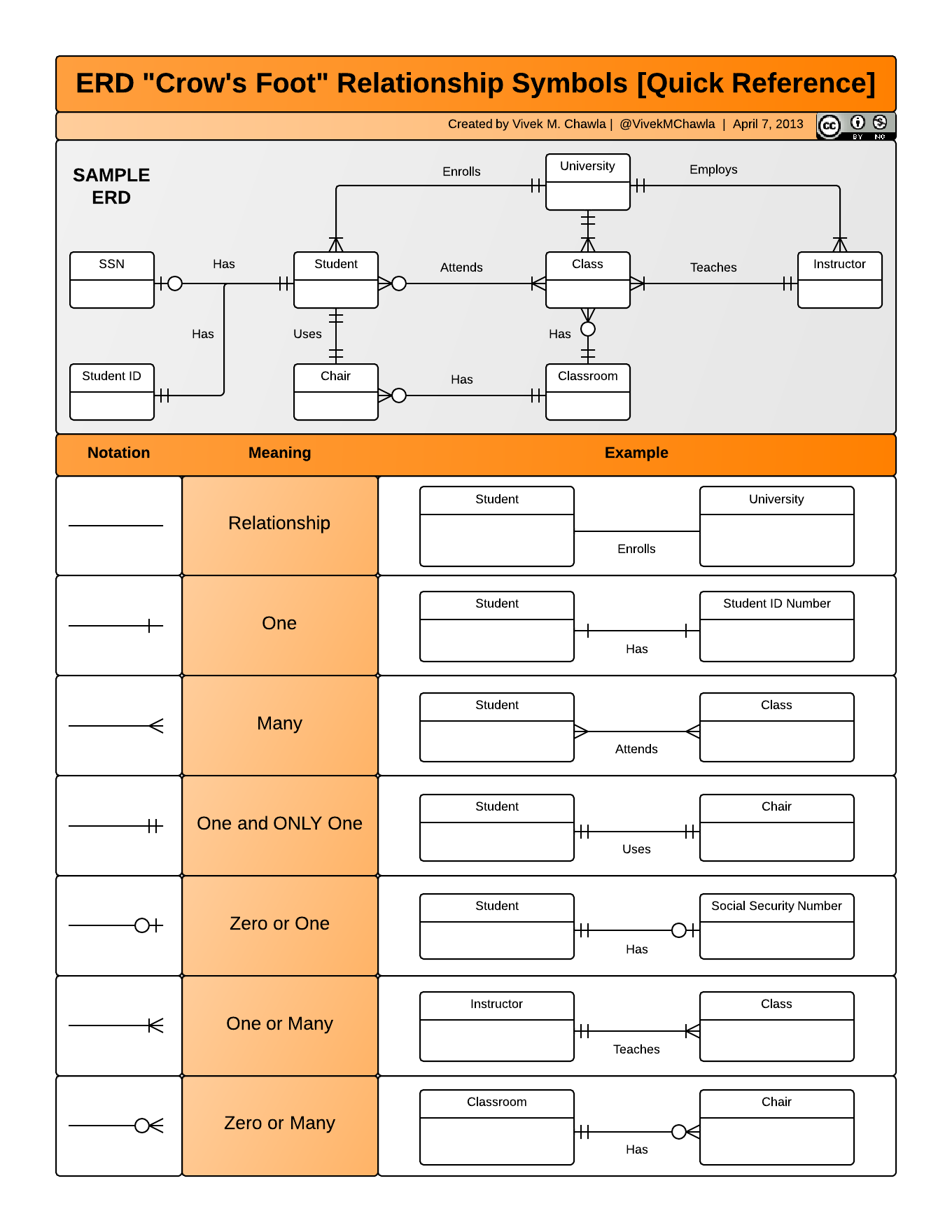
Let's see how these are used in practice.
This video from Decomplexify clearly distinguishes the three basic relationship types using Crow's Foot notation.
Watch the segment from "focus only on the maximum numbers". Pay special attention to the presenter's explanation and diagram for the one-to-one relationship example involving an employee and an ID card.
3. Practical Application: Manager and Department
Let's apply this to a business scenario.
Scenario: A company wants to track which manager is responsible for which department. The business rules are:
- A department must have exactly one manager.
- A manager is in charge of exactly one department.
Let's follow our steps:
- Identify the Entities: The nouns are
DEPARTMENTandMANAGER. - Determine the Relationship:
- Does a
DEPARTMENThave manyMANAGERs? No, it has one. - Does a
MANAGERhave manyDEPARTMENTs? No, they manage one. - This confirms a 1:1 relationship.
- Does a
- Determine Cardinality (Minimum and Maximum):
- From
DEPARTMENTtoMANAGER: The rule "A department must have exactly one manager" means the minimum is 1 and the maximum is 1. The symbol is||(one and only one). - From
MANAGERtoDEPARTMENT: The rule "A manager is in charge of exactly one department" implies this is also mandatory. The minimum is 1 and the maximum is 1. The symbol is||(one and only one).
- From
- Draw the ERD:
A mandatory 1:1 relationship. Each department must have exactly one manager, and each manager must manage exactly one department.
An Example with Optionality
Now, let's adjust the scenario.
New Scenario: An employee in the company may be issued a company laptop. Each company laptop, if issued, is assigned to only one employee.
- Entities:
EMPLOYEE,LAPTOP. - Relationship: 1:1.
- Cardinality:
- From
EMPLOYEEtoLAPTOP: An employee "may be issued" one. This is optional. The minimum is 0, maximum is 1. The symbol is|O(zero or one). - From
LAPTOPtoEMPLOYEE: A laptop "is assigned to only one employee." We'll assume a laptop in this table must be assigned. The minimum is 1, maximum is 1. The symbol is||(one and only one).
- From
- Draw the ERD:
An optional 1:1 relationship. An employee can have zero or one laptop, but a laptop must be assigned to exactly one employee.
4. How Keys Make it Work (A Preview)
In the previous lesson, we established that a 1:M relationship is implemented by placing the primary key of the parent ("one" side) into the child table ("many" side) as a foreign key. How does it work for 1:1? The principle is similar but with a twist to enforce the "one" limit on both sides.
Understanding this is crucial for our next lesson, where we'll focus on correctly placing key indicators on our diagrams.
The video below demonstrates how the optional "health insurance" data from the example at the start of the lesson is separated into its own table and linked back to the main Employee table.
How To Model a One-To-One Relationship in a Database (And Why)
This segment shows the practical step of creating a second table and establishing the foreign key link.
Watch the section from "how do we move these columns". Notice how the primary key of one table is placed in the other as a foreign key to create the link.
As the video shows, we use a foreign key, but to ensure the relationship is truly 1:1 and not 1:M, the database needs an additional rule. There are two common strategies for this, which are explained well in the following reading.
Where to Place the Foreign Key
This reading explains the two main database implementation strategies for creating a 1:1 relationship using keys.
Read the section titled "Where to Place the Foreign Key." Focus on understanding the difference between the two approaches: Foreign key in one of the tables (with a UNIQUE constraint): This is best for optional relationships. Shared primary key: This is used for tightly-coupled, mandatory relationships.
Don't worry about the CREATE TABLE code for now. The key idea to grasp is that the placement and properties of the foreign key are what technically enforce the one-to-one rule you draw in the ERD.
Conclusion
In this lesson, you've added another essential relationship type to your database design toolkit. While less frequent than 1:M relationships, 1:1 relationships are a powerful tool for creating organized, efficient, and secure data models.
Key Takeaways:
- A one-to-one (1:1) relationship links exactly one record from one entity to exactly one record in another.
- They are primarily used to separate optional or sensitive data to improve clarity, performance, and security.
- In Crow's Foot notation, a mandatory 1:1 relationship uses the
||symbol, while an optional one uses the|Osymbol. - A 1:1 relationship is implemented using a foreign key, either with a UNIQUE constraint or as a shared primary key, to enforce the "one" limit on both sides.
You now understand how to model one-to-many and one-to-one relationships. In our next lesson, we will formalize the process of documenting keys in our diagrams by learning how to correctly place primary and foreign key indicators on an ERD.