Hello! In our previous lessons, you learned to draw Entity-Relationship Diagrams (ERDs) for both one-to-many (1:M) and one-to-one (1:1) relationships. You've become comfortable with entities, attributes, and using Crow's Foot notation to show cardinality.
Today, we're going to add a crucial layer of detail to our diagrams. We will focus on how to correctly place primary and foreign key indicators on an ERD. While the lines and symbols show that a relationship exists, it's the keys that provide the technical blueprint for how that link is actually built in the database. Mastering this will make your ERDs far more precise and serve as the foundation for implementing your designs.
1. A Refresher on Primary and Foreign Keys
In previous lessons, we touched on the roles of Primary Keys (PK) and Foreign Keys (FK). Let's start with a clear, formal definition of each and see how they are identified within a set of attributes.
A Primary Key (PK) is an attribute (or a set of attributes) that has a unique value for every single record, or instance, within an entity. Think of it as a student ID number—no two students have the same one.
A Foreign Key (FK) is an attribute in one entity that is a copy of the Primary Key from another entity. It's the "link" that creates the relationship. For example, if we have a STUDENT entity and a COURSE_ENROLLMENT entity, the StudentID would be the PK in STUDENT and an FK in COURSE_ENROLLMENT to show which student is enrolled.
This video provides an excellent review of these concepts and the rules that govern them.
Entity Relationship Diagram (ERD) Tutorial - Part 2: Primary keys, foreign keys, and bridge tables
This video from Lucid Software clearly defines primary and foreign keys and illustrates their roles with a practical e-commerce example.
Please watch the following segments: Begin with the definition and rules of primary keys. See how these rules are applied to select primary keys for the Customer, Order, and Product entities. Next, watch the clear explanation of what a foreign key is and how it links two entities. Finally, understand some key properties of how foreign keys work, especially the fact that they can be repeated.
To reinforce these definitions, especially the role of an FK, let's look at a quick textual summary.
Foreign Key in ER Diagram: A Quick Guide
This article provides a concise written definition of a foreign key and its role in maintaining referential integrity.
Read the first two sections, "What Is a Foreign Key in ER Diagrams?" and the "Example" that follows. This will solidify the concept of the FK in the Orders table referencing the PK in the Customers table.
2. How to Mark Keys on an ERD
Now for the main goal of our lesson: how do we visually represent these keys on our diagrams? While different drawing tools might have slight variations, there are a few widely accepted conventions in Crow's Foot notation.
The most common and clearest method is to add a textual indicator next to the attribute.
- (PK) is used to mark a Primary Key.
- (FK) is used to mark a Foreign Key.
Let's see this in action.
This short clip from the "Decomplexify" video we've seen before gets straight to the point, showing how PK and FK indicators are added to an ERD.
Watch the segment from "adding attributes". Notice how the attributes in each entity are explicitly labeled with "PK" or "FK".
Alternative Notations
Besides the PK/FK labels, you might also encounter notations that use text styling or positional grouping to indicate keys. It's useful to be aware of these as well.
ERD alternatives and variations
This article from Runestone Academy illustrates some common alternative notations for keys.
First, look at the section "Entity-relationship modeling." Notice the first image where the key attribute ID is styled with bold type and underlining. Next, scroll down to the two logical models. See how primary keys are bold and underlined, while foreign keys are italicized. Finally, read the short section "Attributes" and look at the last image. This shows the "PK" and "FK" text indicators we just learned about, and also notes that PKs are sometimes grouped at the top of the attribute list.
For our course, and for your project, using the (PK) and (FK) text indicators is the recommended approach as it is the most explicit and unambiguous.
3. Placing the Keys: Practical Application
Knowing the notation is one thing; knowing where to place the keys is the core skill. The rule is simple and flows directly from the relationship's cardinality:
In a one-to-many (1:M) relationship, the primary key of the "one" side entity is placed as a foreign key in the "many" side entity.
Let's analyze a complete diagram to see this rule in practice.
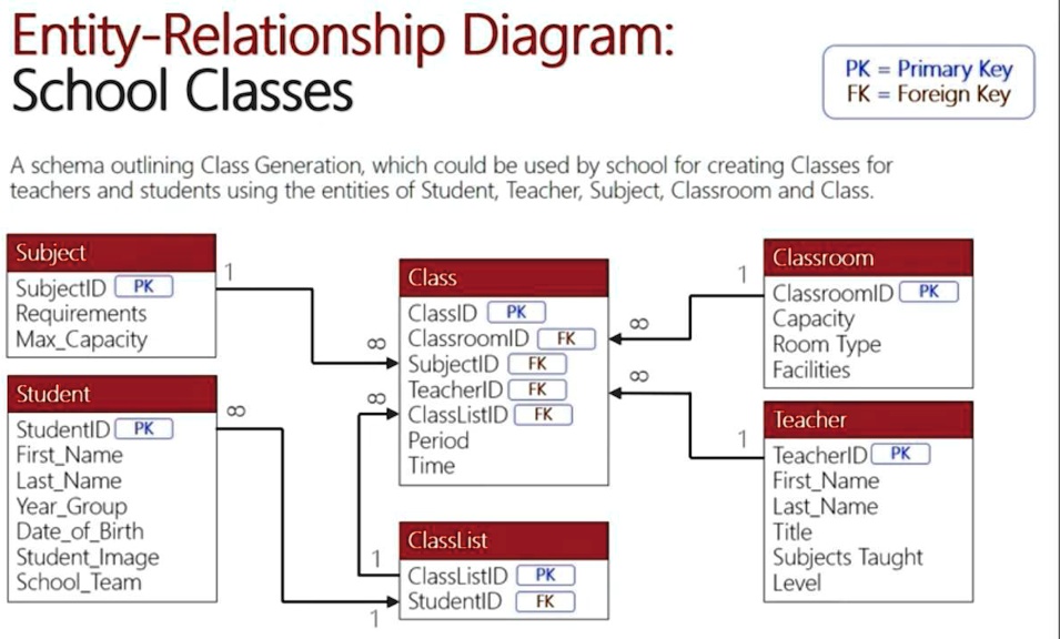
Take a moment to examine the TEACHER and CLASS entities in the "School Classes ERD" above.
TEACHERhas a primary key:TeacherID (PK).CLASShas a primary key:ClassID (PK).- The relationship is that one teacher can teach many classes, but each class is taught by only one teacher (a 1:M relationship).
- To implement this, a copy of the
Teacherentity's primary key (TeacherID) is placed inside theCLASSentity, where it serves as a foreign key (TeacherID (FK)). This successfully links each class record back to a specific teacher record.
Your Turn: Practice Exercise
Now, let's apply this yourself. Consider the following simple scenario for a university.
Scenario:
- We need to store information about
PROFESSORs and theDEPARTMENTs they belong to. - Business Rules:
- A department can have many professors.
- Each professor belongs to only one department.
Your Task:
- Identify the two entities and their attributes from the list below:
DeptIDDeptNameProfIDProfFirstNameProfLastName
- Determine which entity is on the "one" side and which is on the "many" side.
- Draw the two entities using Crow's Foot notation. Inside each entity box, list the appropriate attributes.
- Correctly label the Primary Key (PK) in both entities.
- Add the necessary Foreign Key (FK) to the correct entity to establish the relationship, and label it as
(FK). - Draw the relationship line with the correct cardinality symbols between the two entities.
Take a few minutes to sketch this out on paper or in a simple text editor.
Solution
Here is how the completed ERD should look:

Let's break down the logic using your exercise scenario (PROFESSOR and DEPARTMENT):
- Entities and Attributes:
DEPARTMENT:DeptID,DeptNamePROFESSOR:ProfID,ProfFirstName,ProfLastName
- Relationship: A
DEPARTMENThas manyPROFESSORs ("many" side), and aPROFESSORhas oneDEPARTMENT("one" side). This is a 1:M relationship. - Primary Keys:
- The unique identifier for
DEPARTMENTisDeptID. So,DeptID (PK). - The unique identifier for
PROFESSORisProfID. So,ProfID (PK).
- The unique identifier for
- Foreign Key Placement: Following our rule, we take the primary key of the "one" side (
DEPARTMENT'sDeptID) and place it in the "many" side (PROFESSOR).- The
PROFESSORentity will now have the attributes:ProfID (PK),ProfFirstName,ProfLastName, andDeptID (FK).
- The
This structure allows every professor record to point to the specific department they belong to.
Conclusion
You've now learned the final and most practical step in drawing basic ERDs. By adding key indicators, you transform a conceptual sketch into a technical specification that a database developer can use to build actual tables.
Key Takeaways:
- A Primary Key (PK) uniquely identifies each record in an entity. It must be unique, never-changing, and never null. It is marked with
(PK). - A Foreign Key (FK) is a copy of another entity's primary key, used to establish a relationship. It is marked with
(FK). - The fundamental rule for implementation is: the PK of the "one" side becomes the FK on the "many" side.
- There are multiple notations for keys (PK/FK labels, styling, positioning), but explicit labels are the clearest.
In our next lesson, we will tackle a more complex scenario: the many-to-many (M:N) relationship. You'll discover that these cannot be implemented directly and require a special type of "bridge" entity, known as a composite entity. Your understanding of PKs and FKs will be absolutely essential, as these composite entities have a special kind of primary key built from foreign keys.