Hello! In our last lesson, we identified the fundamental components of an electric circuit: voltage sources that provide energy, and resistors that control the flow of charge. We built an intuition for voltage as a form of "pressure," current as "flow," and resistance as an "opposition" to that flow.
Today, we will connect these three concepts with one of the most important principles in all of electrical engineering: Ohm's Law. This lesson will formalize the relationship between voltage, current, and resistance, giving you a powerful tool to analyze and predict the behavior of simple circuits. By the end of this session, you'll be able to use Ohm's Law to perform basic circuit calculations, a foundational skill for everything that follows.
The Core Relationship: Pressure, Flow, and Restriction
Before we state the law formally, let's solidify the intuition. Your background in mechanical engineering, particularly with fluid dynamics, provides an excellent analogy for understanding how voltage, current, and resistance interact.
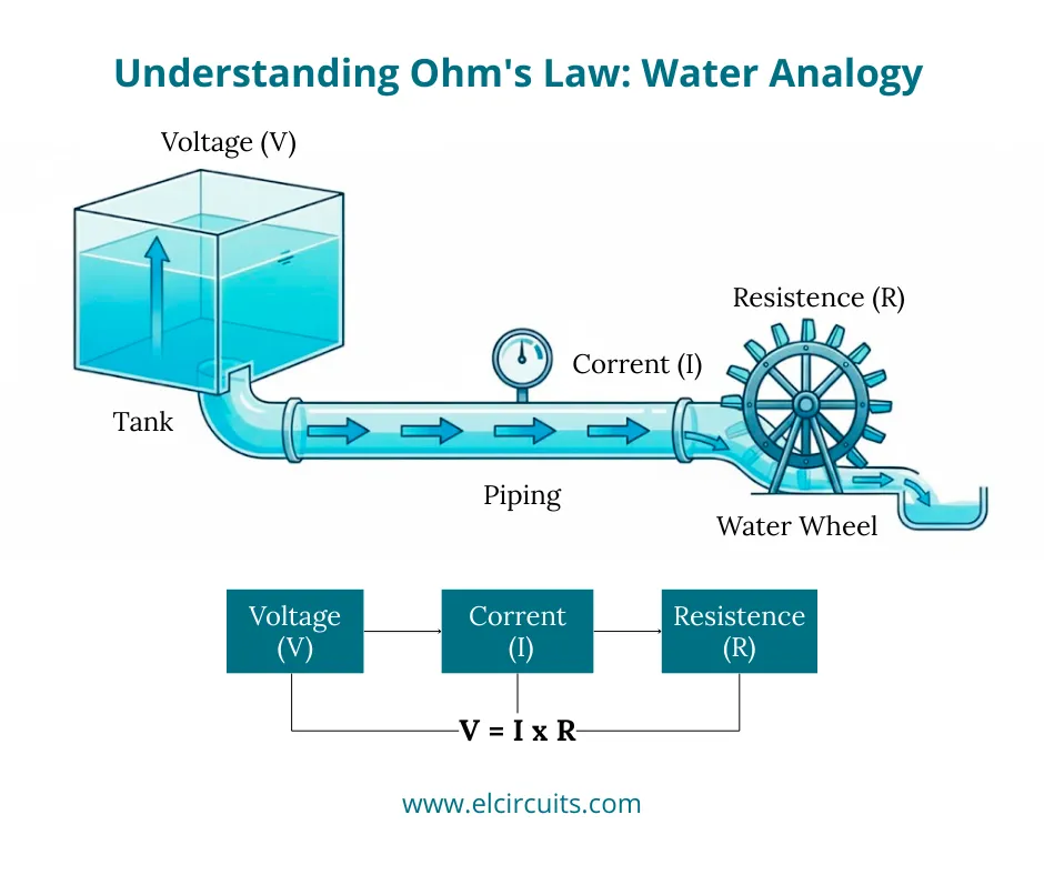
Imagine the system in the image above:
- Voltage (V) is like the water pressure created by the height of the water in the tank. More water in the tank means higher pressure.
- Current (I) is like the flow rate of the water through the pipe. It's the amount of water passing a point per second.
- Resistance (R) is like the narrowness of the pipe or a restriction like the water wheel. It impedes the flow.
Common sense tells us that if you increase the pressure (Voltage), the flow rate (Current) will increase. Conversely, if you make the pipe narrower or add more restriction (increase Resistance), the flow rate (Current) will decrease for the same amount of pressure. This intuitive relationship is precisely what Ohm's Law describes.
Stating Ohm's Law
The German physicist Georg Ohm was the first to formalize this relationship experimentally in the 1820s. He discovered a simple linear equation that connects these three fundamental quantities.
Voltage, Current, Resistance, and Ohm's Law
This article from SparkFun provides a clear and concise introduction to the formula itself.
Please read the section titled "Ohm's Law". It formally presents the equation and uses the water tank analogy to illustrate the mathematical relationship.
As you just read, Ohm's Law is stated as:
Where:
- V is the voltage, measured in Volts (V).
- I is the current, measured in Amperes (A), or "Amps".
- R is the resistance, measured in Ohms (Ω).
This elegant equation is the bedrock of circuit analysis. It tells us that for a given resistance, the voltage across a component is directly proportional to the current flowing through it.
The Ohm's Law Triangle
To make it easy to solve for any of the three variables, engineers often use a simple mnemonic device called the Ohm's Law triangle.
Ohms Law Explained - The basics circuit theory
This video from The Engineering Mindset provides a great visual explanation of the law and the triangle mnemonic.
Please watch from the beginning to the end of the triangle explanation. This will introduce the three forms of the equation and show you how to derive them visually.
By covering the variable you want to solve for in the triangle, the remaining two show you the correct formula:
- To find Voltage (V), cover V: you're left with .
- To find Current (I), cover I: you're left with .
- To find Resistance (R), cover R: you're left with .
Applying Ohm's Law to a Simple Circuit
Now, let's put this law into practice. Consider the simple circuit below, consisting of a battery (voltage source) and a resistor.

Let's assume the battery provides a voltage and the resistor has a resistance . What is the current flowing through the circuit?
Using Ohm's Law:
So, 4 Amperes of current will flow.
What if we keep the same 12V battery but swap the resistor for one with ?
As expected, doubling the resistance (while keeping voltage constant) halves the current.
To see more worked examples and solidify your understanding of these proportional relationships, please continue with the video from The Engineering Mindset.
Ohms Law Explained - The basics circuit theory
This video provides clear, animated examples for calculating each of the three variables.
Please watch the sections on finding voltage, finding current, and finding resistance. Pay close attention to how the circuit's behavior changes when voltage or resistance is doubled.
A Practical Design Example: Protecting an LED
Ohm's Law isn't just for analysis; it's a critical design tool. In your work with medical devices, ensuring components operate within safe limits is paramount. A common task in electronics is choosing a resistor to limit the current flowing through a sensitive component, like a Light-Emitting Diode (LED).
An LED has a maximum current rating. Exceeding it will destroy the device. Let's see how Ohm's Law is used to design a "current-limiting" circuit.
Voltage, Current, Resistance, and Ohm's Law
The SparkFun article provides an excellent, practical walkthrough of this exact design problem.
Please read the section titled "An Ohm's Law Experiment". This will guide you through calculating the correct resistor value to safely power an LED with a 9V battery.
This example is a perfect illustration of engineering design in action. You have a component with known operating constraints (the LED's current rating) and a fixed power source (the 9V battery), and you use Ohm's Law to select another component (the resistor) to make the system work safely and correctly.
A Note on Real-World Behavior
Ohm's Law is an ideal model. It assumes that the resistance (R) is a constant value. For many components, called ohmic devices, this is a very good approximation. However, in the real world, the properties of materials can change with operating conditions. For example, the resistance of a metal filament in a light bulb increases dramatically as it heats up. Such components are called non-ohmic.
This is an important distinction for an engineer. While Ohm's Law provides the foundational relationship, understanding when the model's assumptions might not hold is key to robust design and troubleshooting.
This video demonstrates the difference between a component's calculated resistance and its measured resistance under different conditions.
Please watch the segment from measuring resistance. Notice how the measured resistance of the cold light bulb filament is much lower than the resistance calculated from its operating voltage and current.
Key Takeaways
- Ohm's Law defines the fundamental relationship between voltage, current, and resistance in a circuit: .
- Current is directly proportional to voltage (if R is constant).
- Current is inversely proportional to resistance (if V is constant).
- This law is not just for analysis but is a crucial tool for design, such as calculating the value of a current-limiting resistor to protect a component.
- While Ohm's law is a powerful model, real-world components can be non-ohmic, meaning their resistance can change with conditions like temperature.
You now have the first and most important mathematical tool for analyzing electric circuits. In our next lesson, we will build on this by learning how to calculate the electrical power dissipated by a resistor, connecting the electrical concepts we've learned to the thermal effects you're familiar with from thermodynamics.