Welcome to the second lesson in our exploration of electric circuits. In our previous session, we established a conceptual foundation for charge, voltage, and current, using analogies from mechanics and fluid dynamics to build intuition. We defined voltage as the "push" and current as the "flow" of charge.
Today, we will move from these abstract quantities to the physical components that make up a circuit. This lesson introduces the fundamental building blocks of electrical engineering: the elements that generate, control, and consume electrical energy. You will learn to identify the key players in any circuit diagram: voltage sources, current sources, and resistors. This will equip you with the basic vocabulary needed to read and understand the language of electronics—schematic diagrams.
What is an Electric Circuit?
In the last lesson, we talked about current flowing. For that to happen, we need a complete, unbroken path. An electric circuit is simply a closed-loop path composed of interconnected electrical components that allows electric current to flow.
Think of it as a closed plumbing system. You need a pump to create pressure (our voltage source), pipes to carry the water (wires), and perhaps a narrow section or a turbine that restricts the flow (our resistor). If there's a break anywhere in the loop, the flow stops.
To represent these circuits on paper, engineers use a standardized set of symbols in what is called a schematic diagram. This is a much cleaner and more universal way to represent a circuit than drawing pictures of the components.
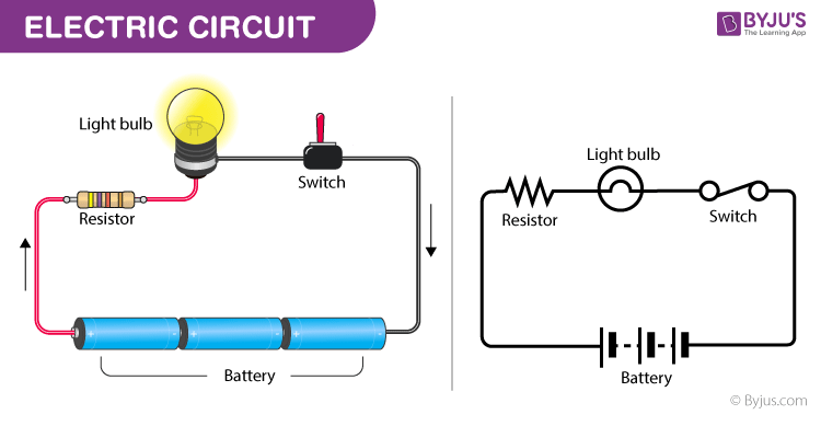
On the left is a pictorial representation of a simple circuit with a battery, switch, resistor, and light bulb. On the right is its corresponding schematic diagram, using universal symbols for each component.
As you can see, the schematic is a functional map of the circuit, not a physical one. Our goal today is to learn the symbols for the most essential of these components.
Active Elements: The Sources of Energy
The components that supply energy to a circuit are called active elements. These are the "pumps" of our system. They come in two primary forms: voltage sources and current sources.
Voltage Sources
A voltage source is a device designed to maintain a fixed voltage across its two terminals, regardless of the amount of current that flows through it. This is the most common type of source you'll encounter. A battery is a perfect example.
Let's refine this definition by distinguishing between the ideal and the practical.
Voltage Source vs Current Source: Definitions, Difference, Example
This article from Wiringuru gives a clear and practical definition of a voltage source.
Please read the first section, What is a Voltage Source?. Pay close attention to the distinction between an ideal voltage source (with zero internal resistance) and a practical voltage source (with some internal resistance).
As you just read, an ideal voltage source is a theoretical concept. In reality, all sources have some internal resistance. This is similar to how a real-world mechanical pump has internal friction and inefficiencies that cause its output pressure to drop as the flow rate increases. For now, in our initial analyses, we will often assume sources are ideal to simplify our understanding.
Common examples of voltage sources include:
- Batteries: Chemical energy is converted to electrical energy to produce a DC (Direct Current) voltage.
- Power Supplies: Devices that plug into the wall and convert AC (Alternating Current) voltage to a stable DC voltage for electronic devices.
- Generators: Mechanical energy (from an engine or turbine) is converted to electrical energy to produce an AC voltage.
The symbols for DC voltage sources are shown below. The one on the left represents a generic source, while the one on the right specifically represents a battery, with the longer line indicating the positive terminal.
Current Sources
The second type of active element is a current source. This is a conceptually different and less intuitive device. A current source is designed to supply a constant current to a circuit, regardless of the voltage that develops across its terminals.
Where a voltage source provides a constant "pressure" and lets the "flow" vary with the load, a current source provides a constant "flow" and adjusts its "pressure" as needed to maintain it.
Voltage Source vs Current Source: Definitions, Difference, Example
Let's return to the same article to understand the current source.
Now, read the second section, What is a Current Source?. Note the key difference in internal resistance: an ideal current source has infinite internal resistance.
While you won't find a "can" of current source on a shelf like a battery, they are fundamental building blocks within more complex electronic circuits. For instance, they are essential for biasing transistors in amplifiers and are used in specialized applications like LED drivers, which need to supply a constant current to maintain consistent brightness.
To solidify the distinction, here is a concise comparison.
Voltage Source vs Current Source: Definitions, Difference, Example
This summary table is an excellent way to consolidate the key differences.
Please review the summary table in the article. Focus on the differences in output, internal resistance, and behavior under dangerous conditions (short vs. open circuit).
The key takeaway is the inverse relationship in their properties and behavior. A voltage source "hates" a short circuit because it will try to supply infinite current to maintain its voltage. A current source "hates" an open circuit because it will try to generate infinite voltage to force its current to flow.
Passive Elements: Resistors
Now that we have sources to provide energy, we need elements to control and use it. The most fundamental of these is the resistor. A passive element like a resistor cannot generate energy; it can only absorb or store it.
A resistor's function is to impede, or resist, the flow of electric current. It does this by converting electrical energy into heat.
How Resistor Work - Unravel the Mysteries of How Resistors Work!
This video from The Engineering Mindset provides an excellent conceptual introduction to how resistors work.
Please watch from the beginning until the end of the analogy. The video explains the purpose of a resistor (e.g., to protect an LED), clarifies the analogy of water flow, and correctly describes resistance as a restriction or "traffic jam" for electrons, not a "speed bump."
As the video explained, resistance is the property of a material that determines how difficult it is for current to pass through. This property is measured in Ohms (Ω).
Resistors are ubiquitous in electronics. They are used to:
- Limit current: To protect sensitive components like LEDs.
- Divide voltage: To create lower voltages from a higher voltage source.
- Dissipate power: In applications like electric heaters.
Your background in quality management and manufacturing processes provides a good parallel here. Just as you might implement process controls or physical constraints to manage the flow of materials or products to ensure quality and prevent system overload, a resistor is an electrical component designed to manage the flow of charge.
The Language of Circuits: Common Symbols
We've now met the three most basic circuit elements. To be able to analyze circuits, you must be able to recognize their symbols. Here is a chart showing some of the most common symbols you'll encounter.
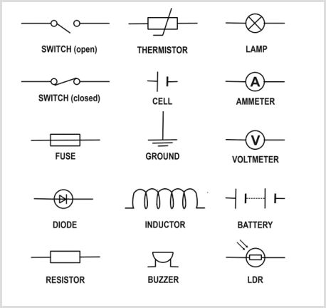
A collection of standard schematic symbols for various electrical components. Today, we have focused on the Resistor, Cell/Battery (Voltage Sources), and the general concept of sources.
Take a moment to locate the symbols for the Resistor, the Cell, the Battery, and the generic Switch. These form the basis of the simple circuit we saw at the beginning.
Key Takeaways
This lesson introduced the fundamental building blocks of electric circuits. Let's summarize:
- An electric circuit is a closed path that allows current to flow, represented by a schematic diagram.
- Voltage Sources are active elements that provide a constant voltage (e.g., batteries, power supplies). An ideal voltage source has zero internal resistance.
- Current Sources are active elements that provide a constant current. They are common inside integrated circuits. An ideal current source has infinite internal resistance.
- Resistors are passive elements that oppose current flow, converting electrical energy into heat. Their resistance is measured in Ohms (Ω).
You are now equipped to identify the key components in a basic circuit diagram. In our next lesson, we will introduce Ohm's Law, the simple but powerful mathematical relationship that connects voltage, current, and resistance. This will be our first step into quantitative circuit analysis.