Hello! Welcome to your next lesson.
In our previous lessons, we built up our understanding of the fundamental properties of electric circuits: voltage, current, resistance, and power. We focused on how these properties manifest in individual components, like a single resistor. Now, we'll shift our focus from individual parts to how they work together in an interconnected system.
Today's lesson introduces the first of two foundational laws that govern all electric circuits: Kirchhoff's Current Law (KCL). This law provides a simple but powerful rule for understanding how current behaves at any junction point within a circuit. Your extensive experience in managing complex systems and processes will serve you well here, as KCL is fundamentally a rule of conservation, a concept that applies across many engineering disciplines. By the end of this lesson, you will be able to state KCL and apply it to find unknown currents at a circuit node.
The Physical Basis of KCL: Conservation of Charge
Before stating the law itself, it's crucial to understand why it works. At its core, KCL is a direct consequence of the physical principle of conservation of charge.
Recall that electric current is the flow of charge (carried by electrons). A node in a circuit is simply a point where two or more wires or components connect—a junction. Since charge cannot be created or destroyed, and because the components of a circuit cannot store charge at a node, the total amount of charge flowing into a node per second must be exactly equal to the total amount of charge flowing out of that node per second.
This idea is very similar to the principle of conservation of mass in fluid dynamics. Imagine a pipe fitting (a "tee" or a "cross") where several pipes join. Assuming no leaks, the total volume of water flowing into that fitting every second must equal the total volume flowing out. The fitting itself doesn't accumulate water. A circuit node behaves in precisely the same way with electric current.
The following short video from Khan Academy does an excellent job of explaining this "common sense" foundation of KCL.
Kirchhoff's current law | Circuit analysis | Electrical engineering | Khan Academy
This video provides the conceptual underpinning for Kirchhoff's Current Law.
Please watch from the beginning until the introduction of the law. Pay close attention to how the law is derived from the basic principle that charge does not "pile up" in a node.
Stating the Law: Two Sides of the Same Coin
As you just saw, the core idea is that "what goes in must come out." We can express this formally in two equivalent ways.
1. The Sum of Currents In Equals the Sum of Currents Out
This is the most intuitive phrasing of the law. For any node in a circuit:
This simply means if you add up all the currents flowing into a junction, the total must equal the sum of all currents flowing out of it.
2. The Algebraic Sum of Currents is Zero
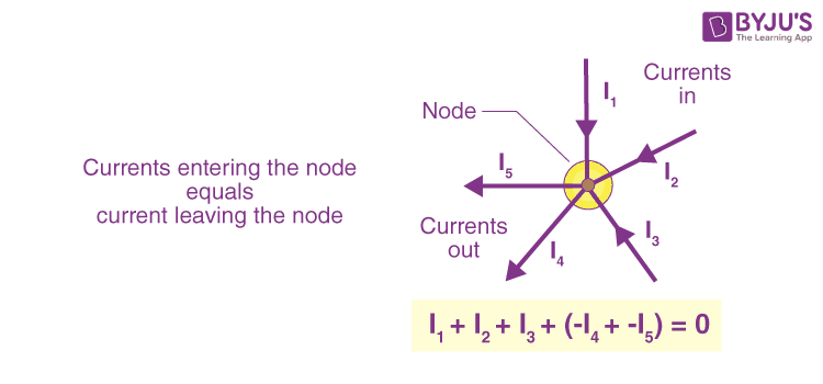
This is the more common form used in circuit analysis because it simplifies the math. For any node, the algebraic sum of all currents entering and leaving is zero:
To use this form, we need a sign convention. The standard convention is:
- Currents entering the node are considered positive (+).
- Currents leaving the node are considered negative (-).
The choice of which direction is positive is arbitrary, as long as you are consistent. You could just as easily define leaving currents as positive and entering as negative; the final answer will be the same.
The image below provides a clear visual summary of a node and the algebraic form of KCL.
To further develop your intuition, particularly from a mechanical engineering perspective, the following resource is highly recommended. It explains KCL using the water pipe analogy we discussed earlier.
This article from All About Circuits provides a clear definition of KCL and reinforces the concept using a parallel circuit and a fluid dynamics analogy.
Please read from the beginning of the article down to the end of the section "Currents Entering and Exiting a Node." The analogy of a "tee" fitting is particularly helpful for visualizing how current splits and merges.
Applying KCL: A Practical Example
Now, let's put the law into practice. Consider the circuit diagram below. We are interested in the currents at node b.

Let's assume we've measured the currents in two of the branches and found that:
- Amperes (entering node b)
- Ampere (entering node b)
Our goal is to find the current , which is shown leaving node b.
Method 1: Using
- Sum of currents in:
- Sum of currents out:
- Setting them equal: . So, the current leaving through the vertical branch is 4 Amperes.
Method 2: Using (Convention: entering is +, leaving is -)
- The equation for node b is:
- Substituting the known values:
- Solving for :
Both methods yield the same result, as expected.
What happens if our initial guess for a current's direction is wrong? Let's say we assumed was leaving the node, not entering. Our algebraic equation would be . If we plug in the magnitude of as 1A, we'd get , which gives . This is incorrect because our initial assumption was wrong. The mathematics of KCL will always give you a consistent answer. If you solve for an unknown current and get a negative value (e.g., ), it simply means the actual direction of that current is opposite to the direction you drew on your diagram.
To see a few more worked examples and solidify your understanding of the sign conventions, please watch the first two problems in this video.
Kirchhoff's Current Law, Junction Rule, KCl Circuits - Physics Problems
This video by The Organic Chemistry Tutor provides clear, step-by-step solutions to KCL problems.
Watch the introduction and the first two examples to see the sign convention in action: Introduction to KCL First example problem Second example problem
Finally, to master the application of sign conventions, especially when the current arrows are pointing in various directions, working through an example is invaluable.
The "concept checks" in this Khan Academy article provide excellent practice for applying KCL with mixed-direction currents.
Please read the section "Kirchhoff's Current Law - concept checks". Follow the author's solution for Problem 3. Notice the strategy of first redrawing the node so all arrows point in the same direction—this is a very effective technique for avoiding sign errors.
Conclusion
In this lesson, we explored Kirchhoff's Current Law (KCL), a fundamental principle for circuit analysis. You now have a conceptual toolset to determine how current is distributed at any junction in a circuit.
Here are the key takeaways:
- Kirchhoff's Current Law (KCL) is based on the principle of conservation of charge.
- A node is a point in a circuit where multiple components or wires connect.
- KCL can be stated in two equivalent ways:
- The sum of currents entering a node equals the sum of currents leaving it ().
- The algebraic sum of all currents at a node is zero (), using a consistent sign convention (e.g., in is +, out is -).
- If you calculate an unknown current and the result is negative, it means the actual flow is in the opposite direction of your initial assumption.
KCL tells us what happens to current at a single point. In our next lesson, we will learn its counterpart, Kirchhoff's Voltage Law (KVL), which describes what happens to voltage as we move around a closed loop in a circuit. Together, KCL and KVL form the essential basis for analyzing even the most complex electrical networks.