Recommended resources
The freely available resources this lesson will direct you to.
Hello! I hope you're ready to put our understanding of the diode to practical use.
In the last lesson, we mastered the Shockley diode equation, which gives us a precise mathematical model for the diode's non-linear I-V curve. We confirmed that a diode allows significant current flow in one direction (forward bias) and blocks it almost completely in the other (reverse bias). Today, we'll exploit this fundamental property to build our first practical diode circuit.
Introduction
Approximate time to complete: 50 minutes
This lesson covers the learning outcome: Diode Application: The Half-Wave Rectifier. Rectification is the process of converting alternating current (AC) into direct current (DC), a cornerstone of nearly all electronic power supplies. The half-wave rectifier is the simplest circuit for this task.
Given your background in radiophysics, you are certainly familiar with the importance of DC power for electronic circuits. This lesson will serve as a practical refresher on how this conversion is first achieved. We will:
- Analyze the operation of the half-wave rectifier circuit, considering both ideal and practical diode models.
- Calculate the key output parameters, including the average DC voltage.
- Derive the formula for the average DC voltage from first principles using calculus.
- Evaluate the rectifier's performance using metrics like Peak Inverse Voltage (PIV), ripple factor, and efficiency.
- Introduce a filter capacitor to improve the output quality.
This lesson forms the basis for understanding more advanced power supply designs and demodulation circuits.
1. The Half-Wave Rectifier: Concept and Operation
The core idea of a half-wave rectifier is simple: place a diode in series with an AC source and a load resistor. The diode will act as a one-way gate, allowing current to flow to the load during one half of the AC cycle and blocking it during the other.
Let's begin by watching a clear explanation of this process. The video first analyzes the circuit with an ideal diode (a perfect switch) and then with a more practical diode that has a forward voltage drop.
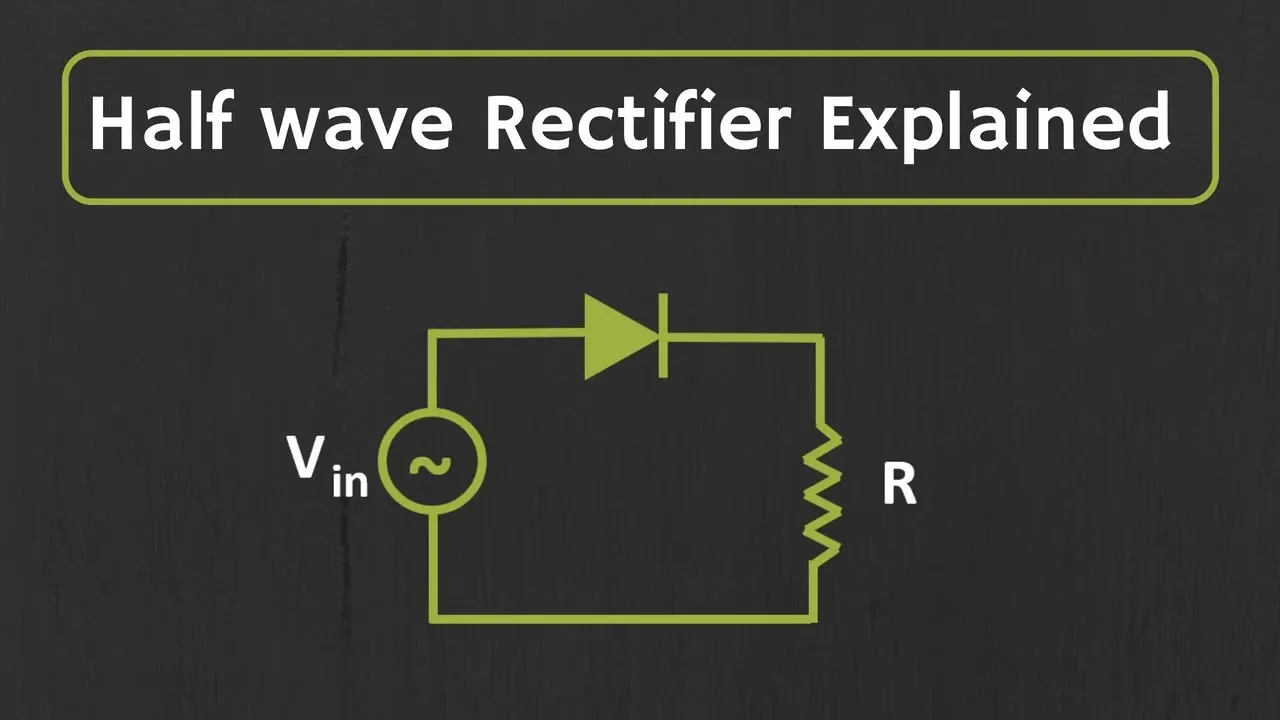
- What to focus on:
- Ideal Diode (1:32 - 3:07): Observe how the diode acts as a closed switch during the positive half-cycle and an open switch during the negative half-cycle.
- Practical Diode (3:07 - 4:42): Pay close attention to how the 0.7V forward voltage drop of a real silicon diode affects the output. Notice that the diode only starts conducting when the input voltage exceeds this threshold, and the peak output voltage is reduced by this amount.
- Time to watch: Approx. 3 minutes.
As you saw, for a practical diode:
- During the positive half-cycle, the diode is forward-biased. Current flows to the load resistor only when the input voltage is greater than the diode's forward voltage drop (approx. 0.7V for silicon). The output voltage is .
- During the negative half-cycle, the diode is reverse-biased, acting as an open switch. No current flows, and the output voltage is zero.
The result is a "pulsating DC" waveform where the negative half of the input AC sine wave has been clipped off.
2. A Complete Circuit and Calculating the Output
In a real-world power supply, the AC source is typically the mains voltage, which is first stepped down to a safer level using a transformer. The output of the transformer's secondary coil then feeds the rectifier.
The following video walks through a complete, practical example, calculating the final average DC voltage from a 120V AC input. This is an excellent exercise that ties together transformer theory, RMS vs. peak voltage, and the rectifier formula.
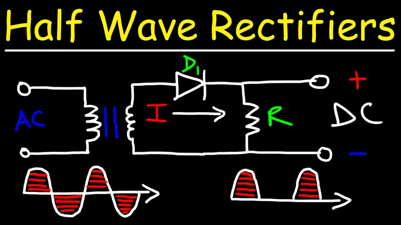
- What to focus on (0:00 - 08:59):
- Circuit & Concept (0:00 - 4:27): Note the complete circuit with the transformer. Also, observe how reversing the diode creates a negative half-wave rectifier.
- Calculation Example (4:27 - 08:59): Follow the calculation step-by-step:
- Calculating the secondary RMS voltage from the transformer ratio.
- Converting RMS voltage to peak voltage ().
- Subtracting the diode's 0.7V drop to find the peak output voltage across the resistor.
- Applying the formula to find the average DC voltage.
- Time to watch: Approx. 9 minutes.
The average value of the pulsating DC output, which is what a DC voltmeter would measure, is given by:
where is the peak voltage across the load resistor, i.e., .
3. Deriving the Average Voltage Formula
You've seen the formula . Given your background, you'll appreciate seeing why this is the case. The average value of any periodic function is its integral over one period, divided by the period.
For our rectified sine wave , the period is . The function is non-zero only from to .
Let's watch the derivation.
- What to focus on (08:59 - 14:06): Follow the integration of the sine wave from 0 to and the subsequent division by the full period . The presenter first derives the result for a full-wave rectifier and then correctly adjusts it for the half-wave case. This is a great preview for our next lesson.
- Time to watch: Approx. 5 minutes.
As the derivation shows, the integral evaluates to:
This confirms our formula and demonstrates its mathematical origin.
4. Performance Metrics and Practical Limits
While simple, the half-wave rectifier has significant drawbacks. We can quantify its performance with a few key metrics. The video we watched earlier introduces these well.
- What to watch:
- Peak Inverse Voltage (PIV) (7:30 - 8:14): This is the maximum reverse voltage the diode must withstand.
- Ripple Factor & Efficiency (8:14 & 12:12): These metrics quantify the "quality" and power conversion capability of the rectifier.
- Time to watch: Approx. 2.5 minutes.
Let's summarize these key metrics:
- Peak Inverse Voltage (PIV): During the negative half-cycle, the full input peak voltage appears across the reverse-biased diode. The diode must be rated to withstand this voltage without breaking down. For a half-wave rectifier, PIV = .
- Ripple Factor (): This measures the "AC-ness" remaining in the output. It's the ratio of the RMS value of the AC component to the DC component of the output voltage. For a half-wave rectifier, (or 121%), which is very high, indicating a poor-quality DC signal.
- Efficiency (): This is the ratio of DC output power to AC input power. For a half-wave rectifier, the maximum theoretical efficiency is only 40.6%. Over half the input power is wasted or contained in the unwanted AC ripple.
5. Improving the Output with a Filter Capacitor
The high ripple is the most obvious problem. A simple and effective way to smooth the pulsating output is to add a large capacitor in parallel with the load resistor. This is often called a "reservoir capacitor."
- What to focus on (09:10 - 12:12): This part of the video brilliantly explains the capacitor's function.
- The capacitor charges quickly to the peak voltage when the diode is conducting.
- When the input voltage falls below the capacitor's voltage, the diode becomes reverse-biased.
- The capacitor then acts as a temporary power source, discharging slowly through the load resistor.
- Time to watch: Approx. 3 minutes.
The slow discharge is key. The rate of discharge depends on the RC time constant (). A larger time constant (large C and/or ) results in a slower discharge and less ripple. The amount of ripple can be approximated by:
where is the frequency of the AC input. This shows that a larger capacitor leads directly to a smaller peak-to-peak ripple voltage, creating a much smoother DC output.
Conclusion
In this lesson, we made the jump from theory to application by building and analyzing the half-wave rectifier. It's the most basic form of AC-to-DC conversion, illustrating the diode's switching capability in a tangible way.
Here are the main takeaways:
- A half-wave rectifier uses a diode's one-way conduction to block half of the AC input cycle, producing a pulsating DC output.
- The average DC output voltage is given by , where accounts for the diode's forward voltage drop.
- A critical design parameter is the Peak Inverse Voltage (PIV), which is equal to the peak input voltage.
- The circuit's performance is poor, with a low efficiency of 40.6% and a high ripple factor of 121%.
- Adding a parallel filter capacitor dramatically smoothes the output by storing charge and supplying it to the load when the diode is off.
Preview of the Next Lesson:
The half-wave rectifier is inefficient and leaves large gaps in the output waveform. How can we do better? In the next lesson, Diode Application: The Full-Wave Rectifier, we will explore clever circuit topologies that utilize both halves of the AC cycle to produce a much more efficient and smoother DC output.