Recommended resources
The freely available resources this lesson will direct you to.
Hello! Following our analysis of the half-wave rectifier, it's time to explore a much more efficient and practical method for AC-to-DC conversion.
In the last lesson, we saw that the half-wave rectifier, while simple, is quite inefficient. It discards half of the input AC waveform, resulting in a low efficiency of only 40.6% and a very high ripple factor of 121%. Today, we will build upon that foundation to construct circuits that utilize the entire AC cycle.
Introduction
Approximate time to complete: 50 minutes
This lesson covers the learning outcome: Diode Application: The Full-Wave Rectifier. Our goal is to understand how to convert AC to DC more efficiently by rectifying both the positive and negative halves of the input sine wave. This is a fundamental technique used in countless power supplies.
Given your background in radiophysics, you'll appreciate how these circuits form the very first stage of almost any piece of electronic equipment that plugs into a wall outlet. We will cover the two primary configurations:
- The Center-Tapped Full-Wave Rectifier: A design using a special transformer and two diodes.
- The Bridge Rectifier: A more common and modern design using a standard transformer and four diodes.
We will analyze the operation of each, compare their characteristics, and quantify their significant performance improvement over the half-wave rectifier.
1. The Center-Tapped Full-Wave Rectifier
One way to rectify both AC half-cycles is to use a transformer with a "center tap" — a connection to the midpoint of the secondary winding. This creates two separate AC voltage sources that are 180 degrees out of phase with each other. We can then use one diode to rectify the top half and a second diode to rectify the bottom half.
Let's watch a detailed explanation of this circuit's operation.
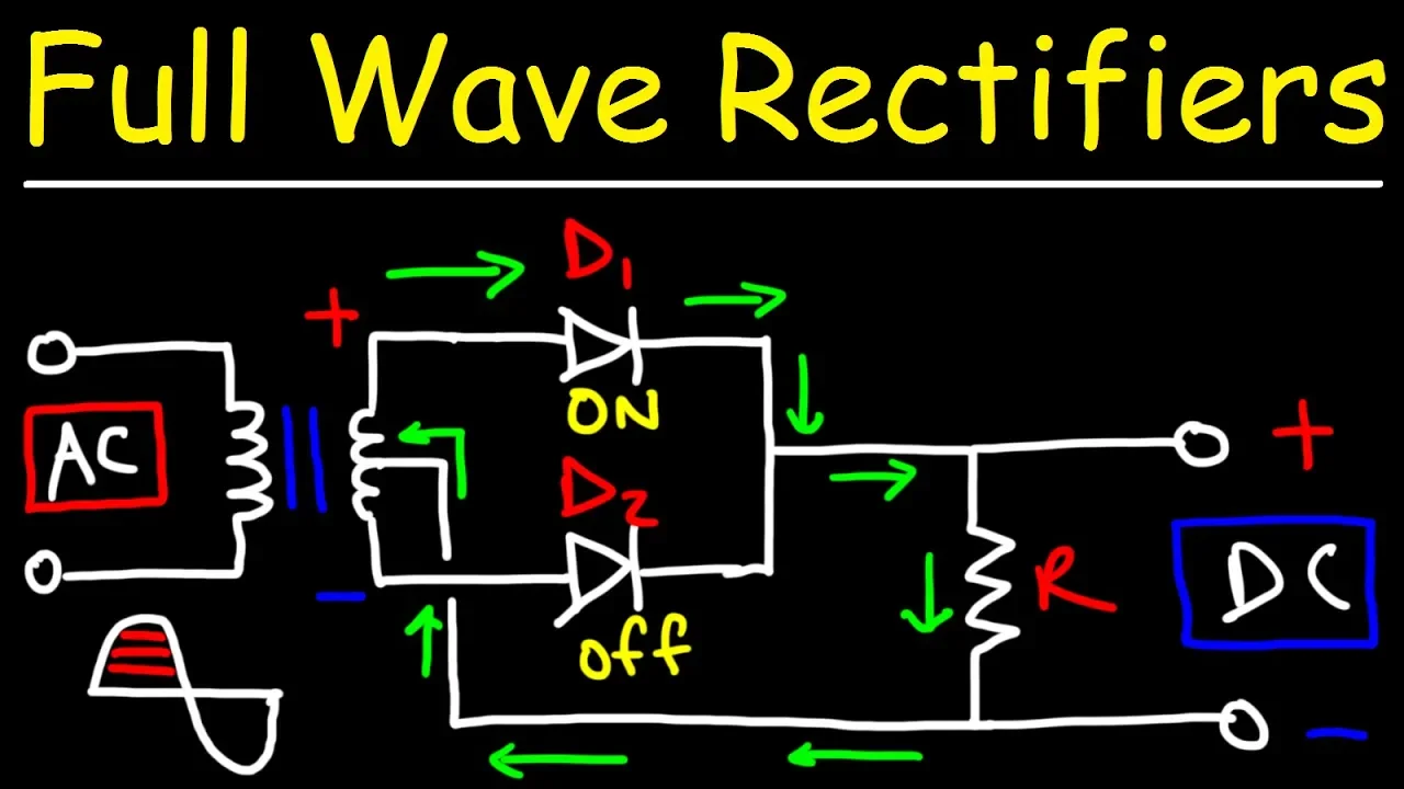
- What to focus on (0:00 - 6:35):
- Circuit Diagram (0:00 - 1:08): Note the key components: a center-tapped transformer, two diodes (D1, D2), and the load resistor (R).
- Positive Half-Cycle (1:08 - 2:51): Follow the current path from the top half of the transformer, through diode D1, down through the load resistor, and back to the center tap. D2 is reverse-biased and off.
- Negative Half-Cycle (2:51 - 4:41): Now, the polarity of the secondary winding is flipped. Follow the current path from the bottom half of the transformer, through diode D2, down through the load resistor, and back to the center tap. D1 is off.
- Combined Output (4:41 - 6:35): Crucially, observe that the current flows through the load resistor in the same direction during both half-cycles. This is the essence of full-wave rectification. The video provides an excellent comparison of the resulting waveform to the half-wave output.
- Time to watch: Approx. 6.5 minutes.
Key Characteristics
The output waveform is now a series of positive-only humps, without the gaps seen in half-wave rectification. This has a profound impact on performance:
- Average DC Voltage: Since we are now utilizing both halves of the wave, the average DC voltage is exactly double that of a half-wave rectifier:
where is the peak voltage across the load resistor. - Peak Output Voltage: In each half-cycle, the current flows through only one diode. The peak output voltage is the peak voltage of half the secondary winding () minus one diode's forward voltage drop ().
- Peak Inverse Voltage (PIV): This is a critical drawback of the center-tapped design. Consider the moment the top half of the secondary is at its positive peak. D1 is conducting, and the voltage at the top of the load resistor is . At this same instant, the bottom half of the secondary is at its negative peak, . The reverse voltage across the non-conducting diode D2 is the difference between these two points: . Therefore, each diode must be able to withstand twice the peak voltage supplied by its half of the winding.
2. The Full-Wave Bridge Rectifier
The center-tapped transformer is bulky and expensive. A more elegant and common solution is the bridge rectifier, which uses four diodes in a clever arrangement to achieve full-wave rectification with a standard, non-tapped transformer.
The following video provides a clear, conceptual review of how this popular circuit works.
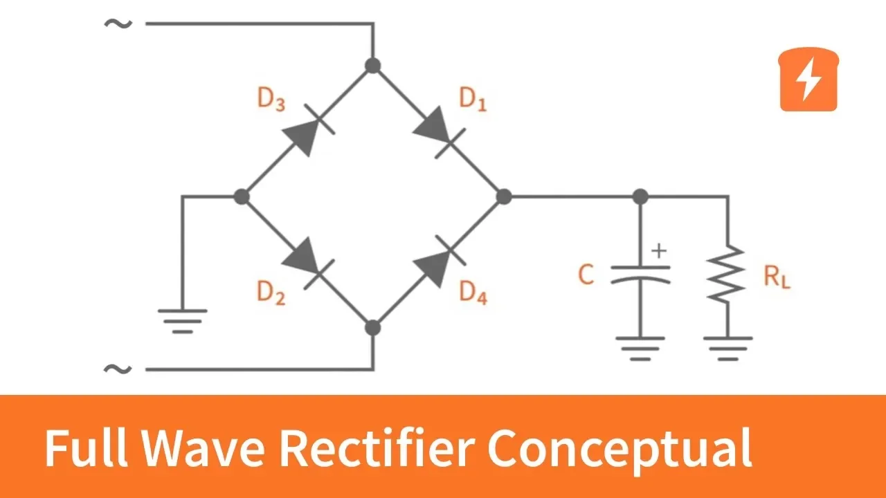
- What to focus on (0:00 - 2:14):
- Introduction (0:00 - 0:56): The video starts by reinforcing why full-wave is preferred and introduces the bridge topology.
- Positive Half-Cycle (0:56 - 1:25): The input's top terminal is positive. Trace the current path through diode D1, down through the load, through diode D2, and back to the negative terminal.
- Negative Half-Cycle (1:25 - 2:14): The input's bottom terminal is now positive. Trace the current path through diode D4, down through the load, through diode D3, and back to the negative terminal.
- Time to watch: Approx. 2.5 minutes.
Notice again that regardless of the input polarity, the current always flows through the load resistor in the same direction. The cost of this design is using four diodes instead of two.
Key Characteristics
- Average DC Voltage: The formula is identical to the center-tapped rectifier: .
- Peak Output Voltage: This is a key difference. In both half-cycles, the current must flow through two forward-biased diodes in series with the load. Therefore, we must subtract two diode drops from the peak secondary voltage.
This point is explained well in the next segment of the video (2:14 - 3:04). - Peak Inverse Voltage (PIV): The bridge rectifier has a significant advantage here. When one pair of diodes is conducting, the other pair is reverse-biased. The reverse voltage across each non-conducting diode is simply the peak voltage across the secondary winding minus one diode drop.
This is roughly half the PIV requirement of the center-tapped design for a similar output voltage, allowing for the use of less expensive diodes. This is covered in the video from 3:04 - 3:29.
3. Performance and Practical Calculation
The full-wave rectifier offers a dramatic improvement in performance metrics:
- Efficiency (): The maximum theoretical efficiency is 81.2%, double that of the half-wave rectifier.
- Ripple Factor (): The ripple factor is 0.48 (or 48%), a significant reduction from 121%. The output is inherently smoother because the fundamental frequency of the ripple is now twice the input AC frequency ().
Let's now walk through a complete calculation for a center-tapped rectifier to solidify these concepts.
- What to focus on (6:35 - 12:01): Follow this excellent step-by-step example. It demonstrates how to go from the primary AC mains voltage to the final average DC output, accounting for:
- The transformer's step-down ratio.
- The use of a center tap (halving the secondary voltage).
- The conversion from RMS to peak voltage.
- The subtraction of the diode's forward voltage drop.
- The final application of the formula.
- Time to watch: Approx. 5.5 minutes.
4. Comparison and Filtering
The choice between a center-tapped and bridge rectifier involves clear trade-offs.
| Feature | Center-Tapped Rectifier | Bridge Rectifier |
|---|---|---|
| Number of Diodes | 2 | 4 |
| Transformer Type | Center-Tapped (bulky) | Standard (cheaper, smaller) |
| Peak Output Voltage | ||
| PIV Requirement | High () | Low () |
| Common Usage | Older designs, some SMPS | Most common type in modern designs |
Due to its advantages, the bridge rectifier is the most widely used configuration for full-wave rectification.
Finally, just as with the half-wave rectifier, we can add a filter capacitor in parallel with the load to smooth the output. The capacitor charges to the peak voltage and discharges slowly through the load. However, because the ripple frequency is now doubled, the capacitor has less time to discharge before the next voltage peak arrives.
This makes filtering much more effective. The peak-to-peak ripple voltage is approximately:
Notice the in the denominator, which confirms that for the same component values, the ripple voltage is halved compared to a half-wave circuit.
Conclusion
In this lesson, we have made a significant leap in rectifier performance by utilizing both halves of the AC cycle.
Key Takeaways:
- Full-wave rectifiers convert both the positive and negative AC half-cycles into a pulsating DC output, doubling the efficiency and halving the ripple compared to half-wave rectifiers.
- The center-tapped rectifier uses two diodes and a special transformer but imposes a high Peak Inverse Voltage (PIV) requirement on the diodes.
- The bridge rectifier is the most common design, using four diodes with a standard transformer and having a much lower PIV requirement.
- The average DC output for any full-wave rectifier is .
- Filtering a full-wave output is more effective because the ripple frequency is twice the input AC frequency, giving the capacitor less time to discharge.
Preview of the Next Lesson:
We have now seen how diodes are fundamental to creating DC power supplies. In the next lesson, "Diode Application: Voltage Clipping and Clamping Circuits," we will shift our focus from power conversion to signal processing, exploring how diodes can be used to shape and modify AC waveforms for applications like signal protection and DC level shifting.