Recommended resources
The freely available resources this lesson will direct you to.
Hello! In the previous lesson, you split a component’s heat between a package-top route and a board route, then followed both routes to the enclosure wall. That calculation produced several temperatures, but a thermal design does not have one universal “safe temperature.” The limit for a semiconductor junction, for example, is not a limit for the PCB or for a surface someone might touch.
Today you will identify five temperature locations—junction, case, board, enclosure surface, and ambient—and match each to the kind of requirement it can legitimately test. This will help you interpret both hand calculations and, later, temperatures reported by Fluent.
Five temperatures, five physical locations
Start at the heat-generating component. Its junction temperature, , refers to the semiconductor die or a specified location within it. The die may have a temperature gradient, so a single reported is a modeling or measurement convention; for thermal protection, the relevant question is usually whether the hottest specified junction location remains within its rating.
The case temperature, , is on the package exterior. It often means the center of the package top, but you must check the measurement definition accompanying a particular specification. It is not the junction temperature: heat crosses package material between the two, and heat may also leave through the leads or underside.
The board temperature, , is measured on the PCB at a stated position near the component. A temperature beside a package is neither the temperature beneath its die nor necessarily the hottest temperature anywhere on the PCB. Probe position matters because the board spreads heat spatially.
Read the following definitions with those distinctions in mind. The purpose is to establish where each temperature belongs, rather than to adopt the illustrated package’s resistance values for your enclosure.
Guidelines for thermal management on STM32 MCUs and MPUs - Application note
Read the thermal-model and temperature-definition passages in STMicroelectronics’ application note. They distinguish die, package-top, board, and surrounding-air temperatures, including measurement-location conventions.
In Section 2.3, “Thermal model of a chip carrier” (pp. 3–4), start with the sentence introducing the simplified package model. Study Figure 2 and the temperature entries in Table 1 through the temperature definitions. Then read Sections 3.1–3.5, “Ambient temperature” through “Board temperature” (pp. 4–5), from ambient through board. Focus particularly on why a temperature name needs a measurement location and test context.
For your sealed enclosure, two more locations complete the picture. The enclosure-surface temperature may mean its inner surface or its outer surface. Specify which one: heat passing through the wall can make them different. An exterior surface can also have a hot spot even when its area-average temperature looks acceptable.
Finally, ambient temperature, , is a temperature of the environment specified for the study—not another name for the enclosure’s internal air. In a sealed enclosure, heat can circulate within the trapped air before passing through the wall to the outside environment. The illustration makes the distinction visible.
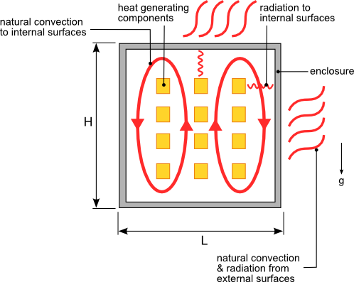
For the hand model used last lesson, these names can be attached to its nodes: the selected component had , , and a board node at . The assumed exterior wall was , while the external ambient was . These are locations in an illustrative model, not five interchangeable readings of one device temperature. In particular, the board node represents the board location chosen for that model, not every point on the PCB.
A limit belongs to a location and an operating condition
A temperature limit is meaningful only when you know what it applies to and under which conditions. A semiconductor’s maximum junction rating protects device operation or reliability. A case-temperature requirement might protect a package, an attached material, or a component characterized using a case measurement. A PCB temperature limit might concern the board laminate, a solder joint, or a nearby temperature-sensitive part; those could require different reporting locations. An accessible exterior enclosure limit may instead concern safe or comfortable contact.
Advanced Energy’s application note provides the safety perspective. Read the enclosure discussion for the categories of surfaces and contact conditions, not to select a numerical limit for this course project: the excerpt refers to particular editions of standards, and the applicable, current requirements must be checked for an actual product.
Design Considerations for Maximum Allowable Temperature
Read Advanced Energy’s discussion of allowable enclosure temperatures to see why an accessible surface has a different constraint from an internal component.
On pp. 3–4, find “ENCLOSURE ALLOWABLE MAXIMUM TEMPERATURES.” Read from its opening explanation through the reminder before the example standards table, enclosure limits. Notice how accessibility, material, and manner of contact change the question being asked; do not treat the example table as a universal design limit.
Ambient is different again. A specified maximum external ambient temperature is ordinarily a required operating condition: the product must meet its other thermal limits while exposed to that environment. It is not evidence that the internal air, case, or junction is allowed to reach that same temperature—or that they will remain at it. Likewise, a calculation performed at ambient does not demonstrate compliance at a specified maximum ambient.
For an upper temperature limit, a useful comparison is the thermal margin
Here both temperatures must describe the same location and operating case. A positive margin meets that particular target in the prediction; a negative margin exceeds it. A positive margin at the junction cannot compensate for an excessive enclosure-surface temperature. Also distinguish a recommended continuous-operating target from an absolute-maximum rating or a fault-condition limit: they answer different engineering questions.
What a case or board measurement can—and cannot—tell you about the junction
The junction is often inaccessible to a surface probe. A case or board measurement can help estimate it, but that estimate needs a package-specific thermal characterization parameter, a defined probe location, and the component’s dissipated power. Texas Instruments’ short explanation contrasts package-top and board measurements with a junction-to-ambient shortcut.
Calculating Temperature of a Device on a PCB (Part 2 of 4)
Watch Texas Instruments’ “Calculating Temperature of a Device on a PCB (Part 2 of 4)” for the difference between measuring a case or board temperature and estimating the hidden junction temperature.
Watch measurement options for the package-top and nearby-board approaches, and the warning about an ambient-based estimate. Then watch metric distinction for why the junction-to-top characterization parameter and junction-to-case thermal resistance should not be treated as interchangeable when heat also leaves through the board. Focus on the differing heat-flow conditions, not on memorizing a parameter value.
For example, a vendor may support an estimate of the form
where is measured at the specified package-top position, is that device’s dissipated power, and is its junction-to-top characterization parameter. It is not simply a series resistance carrying all of : some power can leave by other routes. The applicability of the estimate depends on how closely the actual installation resembles the characterization conditions.
That distinction also explains a trap in the earlier parallel-path calculation. The top-branch rate was not the component’s full . Multiplying a true top-path junction-to-case resistance by would therefore not reproduce that branch’s temperature drop. Conversely, taking a published junction-to-ambient value from a standard test and applying it directly to a sealed enclosure ignores changes to the PCB, internal airflow, radiation, and wall-to-external-ambient path. Those package metrics are useful, but only for the question and conditions they represent.
Turn the five locations into distinct checks
Return to the illustrative temperatures from last lesson. Suppose, solely for this example, that a project has chosen the targets below. They are hypothetical engineering inputs, not limits supplied by the readings or applicable safety standards.
| Check at external ambient | Predicted temperature | Example target | Margin |
|---|---|---|---|
| Selected component junction | maximum | ||
| Specified package-top point | maximum | ||
| Specified board point near component | maximum | ||
| Hottest accessible exterior wall point | * | maximum | * |
*The earlier hand calculation used one wall temperature. It did not establish that is the wall’s hottest accessible point, so this last margin is provisional.
This comparison reveals two practical issues. First, the junction has the largest numerical margin here, but that says nothing about whether the tighter board or enclosure targets will hold. Second, report definitions are part of the requirement. A future Fluent model could report a maximum temperature over a represented die, a package-top temperature at a defined point or region, a nearby-board probe temperature, and a maximum over accessible exterior wall faces. Reporting only one overall maximum temperature would not answer all four questions. If the component is represented as a simple solid block rather than a resolved die and package, its computed block temperature must not be silently relabeled as a junction prediction.
The example also says nothing yet about a higher design ambient. It would need to be recalculated at that ambient, with the specified component powers and exterior conditions, before its margins could be claimed for that case.
Closing perspective
Junction, case, board, enclosure surface, and ambient name different physical locations. Junction limits concern the die; case and board checks require defined measurement positions; enclosure limits require the correct inner or outer surface and, for accessible surfaces, the relevant contact requirement. External ambient defines the environment in which those checks must pass. Compare every predicted temperature with a limit for the same location, operating condition, and reporting convention.
In the next lesson, you will turn these distinctions into measurable simulation outputs and explicit thermal acceptance criteria for the enclosure study.