Recommended resources
The freely available resources this lesson will direct you to.
- Demystifying NCCL An In depth Analysis of GPU Communication Protocols and Algorithms - Zhiyi Huwww.youtube.com
- Efficient Large-Scale Language Model Training on GPU Clusterswww.youtube.com
- RoCE networks for distributed AI training at scaleengineering.fb.com
- NCCL Deep Dive: Cross Data Center Communication and Network ...developer.nvidia.com
Introduction
In our previous lesson, we analyzed strong and weak scaling, establishing that communication overhead—the "serial fraction" in Amdahl's Law—is a primary obstacle to achieving ideal performance as we add more GPUs. A key part of this overhead comes from collective communication operations like AllReduce, which synchronize data across all processors.
Today, we directly address this bottleneck. This lesson covers the learning outcome: Describe how topology-aware task placement can optimize collective communication performance. We will investigate how the physical layout and connectivity of GPUs in a cluster, known as the network topology, can be intelligently used to place distributed tasks. By mapping the communication patterns of our algorithms to the high-bandwidth paths in the hardware, we can significantly reduce communication latency and improve overall scaling efficiency. This is a core principle in high-performance system design for AI.
Understanding Network Topology in GPU Clusters
In a modern data center, not all network links are created equal. Communication speed and bandwidth vary dramatically depending on whether data is moving between GPUs inside the same physical server, between servers in the same rack, or between different racks. This hierarchical structure is the network topology.
A typical GPU cluster topology has several tiers of connectivity:
- Intra-Node: GPUs within a single server are often connected by ultra-high-bandwidth, low-latency interconnects like NVIDIA's NVLink. This is the fastest communication path.
- Intra-Rack: Servers within the same rack are connected via a Rack Switch (e.g., an RTSW or Top-of-Rack switch). This connection, typically over Ethernet or InfiniBand, is slower than NVLink but faster than communicating with a different rack.
- Inter-Rack / Cluster-Level: Racks are interconnected through higher-level fabric switches (e.g., Spine switches or CTSWs). These links are often oversubscribed, meaning the total potential bandwidth of all racks exceeds the switch's capacity, making this the most likely bottleneck for large-scale communication.
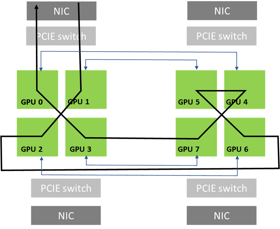
The following image shows a simplified view of how GPUs connect within a server and to the wider network. The thick lines suggest high-bandwidth intra-node links (like NVLink), while the connections to NICs (Network Interface Cards) represent the path to other servers.
To understand how this looks at a massive scale, let's examine how a hyperscaler like Meta designs its network.
RoCE networks for distributed AI training at scale
This article from Meta Engineering describes the design of their specialized backend network for AI training. It provides a real-world example of a hierarchical cluster topology.
Please read the initial sections, starting from the introduction down to the end of the 'AI Zone' subsection. Focus on understanding the hierarchy: Frontend vs. Backend Networks: The separation of concerns for data ingestion and training traffic. AI Zone: The two-stage Clos topology composed of Rack Training Switches (RTSW) and Cluster Training Switches (CTSW). Aggregator Layer (ATSW): The mechanism to connect multiple AI Zones for even larger jobs. \nThis describes a physical reality where communication within an AI Zone is faster and has more bandwidth than communication across AI Zones.
The key takeaway is that network performance is non-uniform. The "cost" of sending a message between two GPUs depends on their physical placement. A topology-unaware system treats all GPU-to-GPU communication as equal, which can lead to severe performance degradation.
The Impact of "Unaware" Placement on Collectives
Collective communication algorithms, like the Ring-AllReduce we've discussed, impose a logical communication pattern on the GPUs. In a ring, each GPU (or rank) only ever communicates with its two immediate neighbors.
Let's see how Ring-AllReduce works step-by-step.
Demystifying NCCL An In depth Analysis of GPU Communication Protocols and Algorithms - Zhiyi Hu
This video provides a deep dive into the NCCL library. This specific segment gives a clear, visual walkthrough of the Ring-AllReduce algorithm.
Watch the segment from 12:56 to 16:11. You don't need to absorb every detail of the primitives, but focus on the animation starting around 14:15. Notice how each GPU repeatedly sends a chunk of data to its right neighbor in the logical ring, receives from its left, performs a computation, and repeats. The performance of the entire ring is dictated by the slowest link in that cycle.
Now, consider the implication: if a scheduler places two logically adjacent ranks (e.g., rank 3 and rank 4) on two physically distant GPUs (e.g., in different racks or even different AI Zones), every single step of the ring algorithm will have to traverse that slow, high-latency link. Since all ranks operate in lockstep, the entire collective operation is bottlenecked by this single poor placement choice.
Topology-Aware Task Placement: The Solution
Topology-aware task placement solves this problem by aligning the logical communication graph of the application with the physical network topology. The goal is to ensure that frequent or high-bandwidth communication happens over the fastest available links.
This is typically handled by two main components of the system: the job scheduler and the communication library (e.g., NCCL).
1. The Role of the Job Scheduler
A smart, topology-aware scheduler (like Slurm or a custom in-house scheduler) has access to the physical layout of the cluster. When a user requests 16 GPUs for a job, the scheduler's goal is to allocate 16 GPUs that are "close" to each other.
- Ideal Case: Allocate two full 8-GPU servers connected with NVLink.
- Good Case: Allocate 16 GPUs that are all within the same rack.
- Sub-optimal (but managed) Case: If the job must span multiple racks or AI Zones, the scheduler should choose them strategically to minimize the traffic crossing the oversubscribed inter-zone links.
Meta's engineering blog provides a perfect, concise description of this strategy.
RoCE networks for distributed AI training at scale
Let's return to the Meta article. This short section explicitly describes how their scheduler uses topology information.
Read the paragraph immediately under the 'AI Zone' diagram. It describes finding a 'minimum cut' to reduce cross-AI Zone traffic and recommending a rank assignment. This is the essence of topology-aware scheduling.
This "minimum cut" approach is a classic graph partitioning problem. The scheduler aims to place the ranks of a job in a way that the communication crossing the boundary between slower network domains (the "cut") is minimized.
2. The Role of the Communication Library
Even with a good physical allocation from the scheduler, the communication library itself can further optimize performance. NCCL, for instance, can discover the local network topology and re-order the ranks to build more efficient communication structures.
Imagine the scheduler gives your job two 8-GPU servers. It might assign ranks 0-7 to server A and 8-15 to server B. A naive Ring-AllReduce would create a single ring: 0-1-...-7-8-...-15-0. This ring has two slow inter-server hops (7 -> 8 and 15 -> 0).
A topology-aware NCCL can do better. It identifies that there are two distinct locality groups (the two servers). Instead of one large ring, it can construct the collective operation more intelligently.
The following article from NVIDIA explains how NCCL implements this.
NCCL Deep Dive: Cross Data Center Communication and Network Topology Awareness
This NVIDIA Developer Blog post details how NCCL was enhanced to become topology-aware, particularly for communication spanning multiple data centers (a macro version of spanning multiple racks).
Please read the following two sections: 'Step 2: NCCL discovers the network topology through the fabric ID': This explains the mechanism (fabricId) NCCL uses to learn about the network connectivity between GPUs. You don't need to memorize the environment variables, just understand the concept of assigning an ID to different network domains (e.g., DC_ID, RAIL_ID). 'Step 3: Network topology guided algorithms': This is the core of the lesson. Pay close attention to how the Ring algorithm is modified. NCCL first builds rings within each data center (or locality group) and then connects the 'loose ends' to cross the slower link. This ensures the slow link is traversed only a minimal number of times. The discussion on the Tree algorithm follows a similar principle.
The NCCL approach of building intra-DC rings and then linking them is a powerful optimization. For our 16-GPU example on two servers, it would effectively create two fast 8-GPU rings running in parallel internally on each server, with communication between the servers only happening at the "root" or junction points of these rings. This dramatically reduces the traffic on the slower inter-server link.
The article also mentions "scattering," which is an even more advanced technique. If multiple inter-domain links are available, NCCL can spread the communication across them to avoid bottlenecking a single link.

Conclusion
In this lesson, we've connected the theoretical problem of communication overhead to a concrete, practical systems solution. By understanding and exploiting the non-uniform nature of data center networks, we can significantly improve the performance of distributed training jobs.
Key Takeaways:
- Network Topology is Hierarchical: GPU clusters have distinct performance tiers: fast intra-node links (NVLink), medium-speed intra-rack links, and slower, often oversubscribed, inter-rack or inter-zone links.
- Placement Dictates Performance: The performance of a collective operation is limited by the slowest link it must traverse. A topology-unaware placement of tasks can inadvertently force high-frequency communication over slow links, creating a major bottleneck.
- Topology-Awareness is the Solution: Both job schedulers and communication libraries can use knowledge of the network topology to optimize performance.
- Schedulers aim to allocate physically "close" resources to a single job, treating it as a graph-partitioning problem to find a "minimum cut."
- Libraries like NCCL can discover the local topology and restructure collective algorithms (like Ring-AllReduce) to minimize traffic on slow links, for example, by building local rings and then connecting them.
This strategy is fundamental to achieving high scaling efficiency and is a critical consideration in the design of any large-scale AI training system.
Preview of the Next Lesson:
Having optimized our job's performance by placing it intelligently on the hardware, we now turn to another critical set of constraints at scale. In the next lesson, we will address the learning outcome: "Describe the key power and cooling considerations in designing and operating large-scale GPU deployments." We will see that once you can run computations fast, keeping the system powered and preventing it from overheating becomes the next major engineering challenge.